28
2. Select Off and press . This will disable external analog control. To enable, select
any of the three other menu items and press after selection.
3. When finished, press several times to exit the menu.
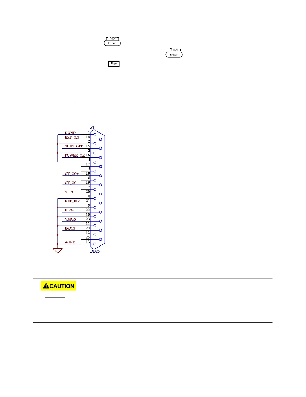
Pin Assignment
Below are the pin assignments of the analog interface.
Figure 3.3 - Analog Interface Pin Assignments
Pin # Label Description
1 DGND Ground pin
14 EXT ON Control output state
15 SHUT_OFF Emergency shut off
16 POWER_OK Status output
18 CV_CC+ CV mode status
19 CV_CC- CC mode status
20 VPRG Voltage programming input
21 REF_10V 10V DC reference output
22 IPRG Current programming input
23 VMON Voltage monitoring output
24 IMON Current monitoring output
13 AGND Ground pin
DO NOT input any voltages above 10 V DC or 10 kΩ resistance or below 0 V DC to any of
the 25 pins. Doing so will damage the power supply. The inputs also do not have reverse
polarity protection. Check your positive and negative connections carefully first before
feeding power into the control pins.
Control Output State