54
RS-485
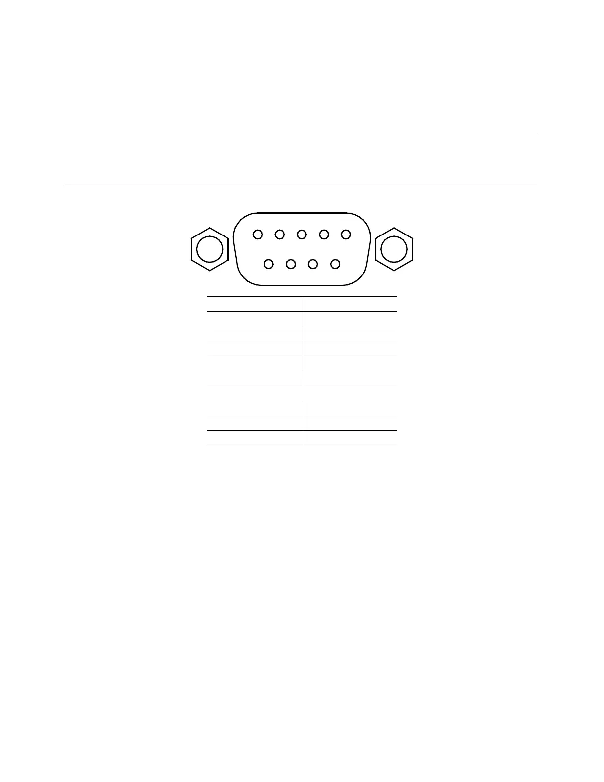
For multi-unit configuration and control, the male DB-9 interface labeled RS-485 in the rear
panel is used. The figure below illustrates the connection pins and description.
Note: Pin 1 is used as the A pin (-) (non-inverting).
Pin 5 is used as the B pin (+) (inverting).
SC (reference) pin is not used.
USBTMC
The device is SR1, RL1, and DT1 enabled. It can receive the following request:
REN_CONTROL, GO_TO_LOCAL, LOCAL_LOCKOUT. When it receives MsgID = TRIGGER USBTMC
command, it will transmit TRIGGER command to the function layer.