11
Do not connect power to the instrument until the line
voltage selection is setup correctly. Applying an
incorrect line voltage or configuring the line voltage
selection improperly may damage the instrument and
void all warranty.
Any disassembling of the case or changing the fuse
not performed by an authorized service technician
will void the warranty of the instrument.
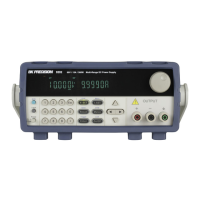
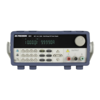
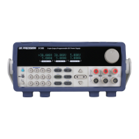
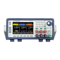
2.3 Output Connections
The main DC output terminal is a binding post terminal on the front panel.
Due to the high current rating of the power supply, proper wire sizes are necessary for safe
connectivity and to prevent wires from overheating. Refer to the table below as a reference for
proper wire sizes according to the amount of current used for operation:
Table 2 - Wire Gauge Rating
Before connecting wires to the output terminals, turn
OFF the power supply to avoid damage to the
instrument and the device under test (DUT). For
safety, load wires must have a wire gauge size large
enough to prevent overheating when the power
supply operates at maximum short circuit output
current. It will also prevent large voltage drops from
resistances in the wires.
Hazardous voltages may exist at the outputs and the
load connections when using a power supply with a
w ww . . co m
information@itm.com1.800.561.8187