Page 4 RELM Wireless
KNG MOBILE INSTALLATION GUIDE
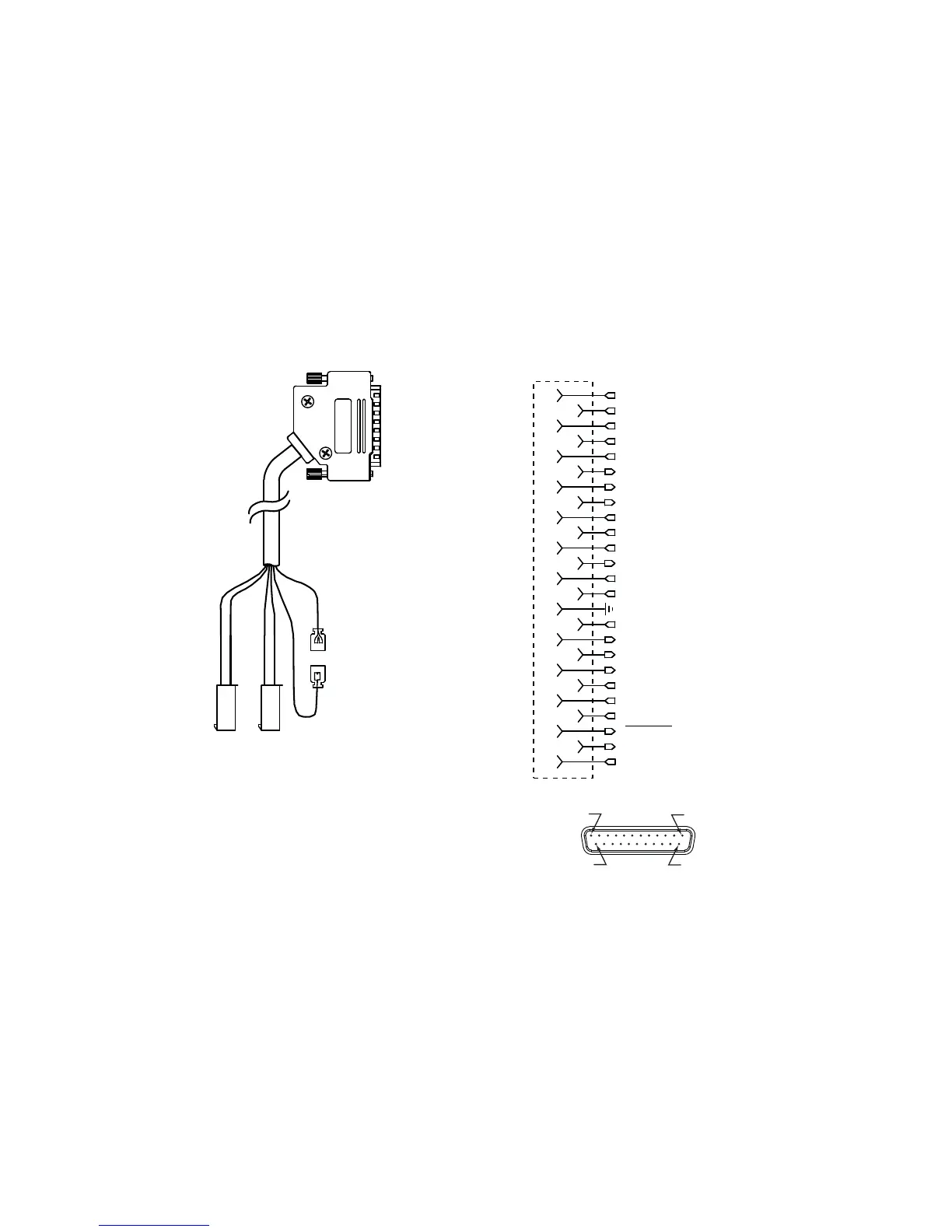
If vehicle ignition control of radio power up/power down is to be used, 5.
connect the red/white ignition sense line from the accessory cable to the
vehicle’s ignition. Leave the red wire disconnected. (See fi gure 2)
IMPORTANT: IF IGNITION SENSE WILL NOT BE USED, THE RED WIRE
MUST BE CONNECTED TO THE RED/WHITE WIRE OR THE RADIO
WILL NOT POWER-UP.
Route and connect any required accessory option controls to the accessory 6.
cable.
Pin 25
Pin 13
Pin 1
Pin 14
1
2
3
4
5
6
7
8
9
10
11
12
13
13
15
16
17
18
19
20
21
22
23
24
25
SPKR1+
SPKR1-
RF_USB_HOST_PWR
RF_USB_HOST_D+
RF_USB_HOST_D-
ACC_RS232_TXD
ACC_RS232_RTS
ACC_RS232_DSR
ACC_RS232_CTS
ACC_RS232_RXD
ACC_AUDIO_OUT
ACC_MIC
LOW_CURRENT_A+_OUT
FUSED_SWA+
IGNITION_SENS
EXT_EMERGENCY_INPUT
OPT_1_INPUT
OPT_2_INPUT
AUX_1_OUTPUT
AUX_2_OUTPUT
AUX_3_OUTPUT
ACC_PTT
SPKR2-
SPKR2+
Red Wire
(Fused A+, Pin 20)
See Note 1
Red/White Wire
(Ignition Sense, Pin 21)
See Note 1
NOTE 1: To enable vehichle ignition control ot
radio power up/power down, connect the
red/white ignition sense line to the vehichle’s
ignition. Leave the red wire discontected.
If ignition control is not used connect the red/white
wire to the Red wire.
REMOTE CONTROL HEADS DO NOT USE THIS
CONNECTION
Relalys connected to Option outputs
3, 4 or 5 must be powered from fused A+
Figure 2 - Accessory Cable and Connections
Install your RF antenna and route the cable to the back of the dash mount/7.
radio core install location.
Install the GPS antenna (if used) and route the cable to the back of the 8.
dash mount/radio core install location.
 Loading...