RELM Wireless Page 7
KNG MOBILE INSTALLATION GUIDE
Attach and secure the accessory connector with a small fl at blade screw 4.
driver.
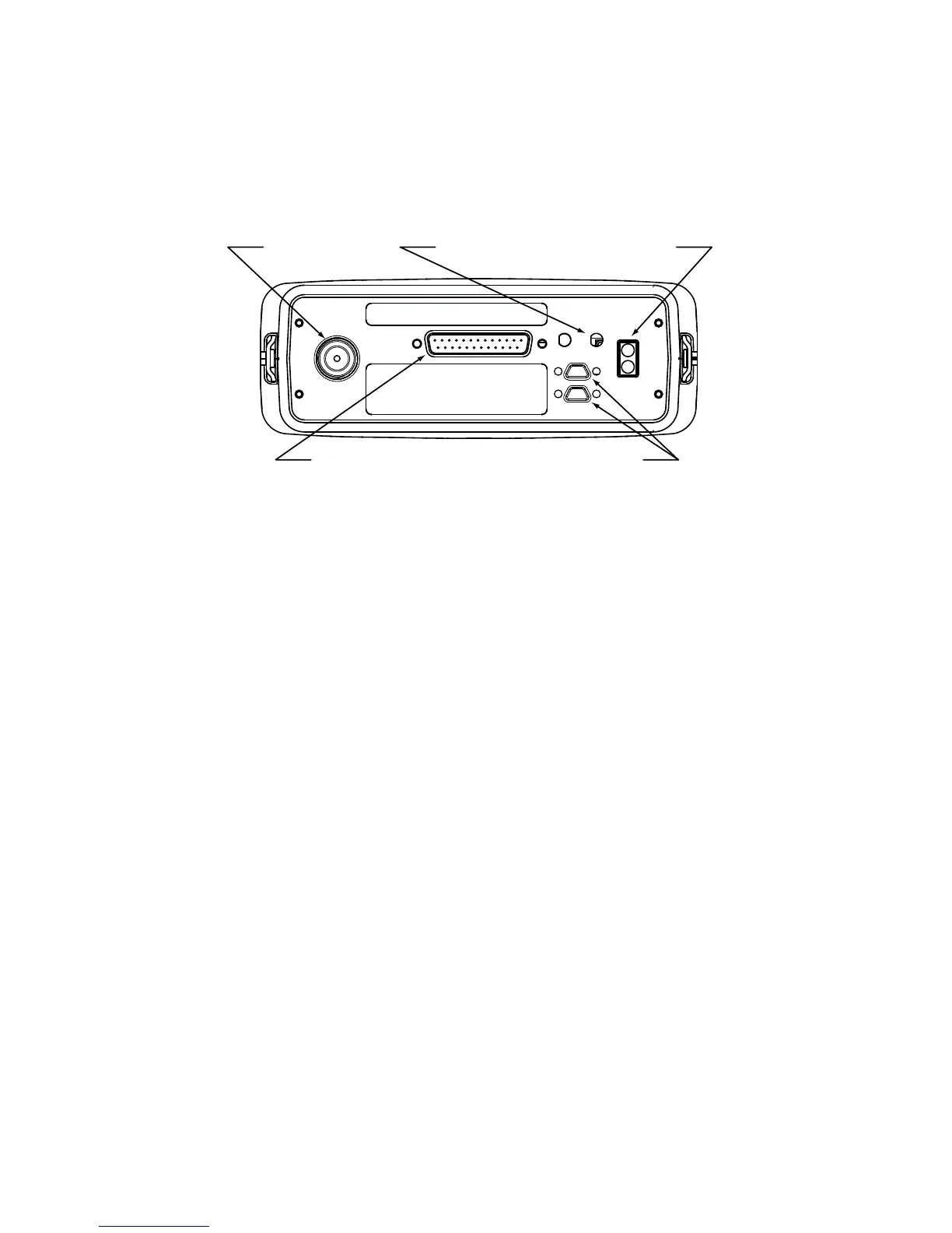
Attach the RF antenna (and GPS antenna if used) to the radio’s antenna 5.
port(s). (See fi gure 5)
Connect the power cable assembly to the DC Power input connection.6.
GPS Antenna Port
Type - MMCX
RF Antenna Port
Type - MMCX
Accessory Connector
Remote Head Connectors
DC Power
Connection
Figure 5 - Dash Mount/Radio Core Back Panel Connections
Position the radio into the bracket at the desired angle. 7.
Install and tighten the 4 mounting knobs (Item 2).8.
4.4 REMOTE-MOUNT CONTROL HEAD INSTALLATION
Installation of a KNG remote control head requires install kit KAA0638 hardware
kit and the proper cable kit to provide adequate cable for installation.
Remote Cable Kit Part Numbers
KAA0635 - 8 foot remote cable assembly•
KAA0636 - 17 foot remote assembly•
KAA0637 - 25 foot remote assembly•
Optional Equipment
KAA0261 Speaker Kit•
Prep the remote head power cable as described in Section 4.11.
Route the remote cable from the radio core location to the remote head 2.
location.
Attach the cable to one of the two remote head connectors on the back of 3.
the main unit. (See Figure 5).
Secure the remote cable with a small fl at blade screw driver.4.
Drill 1/4” pilot holes through the mounting plate. A minimum of four holes is 5.
recommended. A mounting template can be found on page 13 or use the
 Loading...