EasyManua.ls Logo

Black & Decker BD200SD - User Manual

Black & Decker BD200SD
60 pages
Print Icon
To Next Page IconTo Next Page
Loading...
VEA EL ESPAÑOL EN LA CONTRAPORTADA.
POUR LE FRANÇAIS, VOIR LA COUVERTURE ARRIÈRE.
SAVE THIS MANUAL FOR FUTURE REFERENCE.
INSTRUCTIVO DE OPERACIÓN, CENTROS DE SERVICIO Y
PÓLIZA DE GARANTÍA. ADVERTENCIA: LÉASE ESTE
INSTRUCTIVO ANTES DE USAR EL PRODUCTO.
INSTRUCTION MANUAL
BB
BB
DD
DD
22
22
00
00
00
00
SS
SS
DD
DD
11
11
00
00
ii
ii
nn
nn
((
((
22
22
55
55
44
44
MM
MM
MM
MM
))
))
TT
TT
AA
AA
BB
BB
LL
LL
EE
EE
SS
SS
AA
AA
WW
WW
BEFORE RETURNING THIS PRODUCT FOR ANY
REASON PLEASE CALL 1-800-544-6986
BEFORE YOU CALL, HAVE THE FOLLOWING INFORMATION AVAILABLE, CATALOG NO., TYPE NO., AND DATE CODE . IN MOST
CASES, A BLACK & DECKER REPRESENTATIVE CAN RESOLVE THE PROBLEM OVER THE PHONE. IF YOU HAVE A
SUGGESTION OR COMMENT, GIVE US A CALL. YOUR FEEDBACK IS VITAL TO BLACK & DECKER.
T
T
HANK
HANK
YOU
YOU
FOR
FOR
CHOOSING
CHOOSING
B
B
LACK
LACK
& D
& D
ECKER
ECKER
!
!
G
G
O
O
T
T
O
O
WWW
WWW
.B
.B
LACKAND
LACKAND
D
D
ECKER
ECKER
.
.
COM
COM
/N
/N
EW
EW
O
O
WNER
WNER
T
T
O
O
REGISTER
REGISTER
YOUR
YOUR
NEW
NEW
PRODUCT
PRODUCT
.
.
Question and Answer IconNeed help?

Do you have a question about the Black & Decker BD200SD and is the answer not in the manual?

Overview

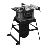
This document describes the Black & Decker BD200SD 10-inch (254mm) Table Saw, a motorized bench saw designed for high-quality performance and versatile cutting operations.

Functional Description:

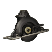
The BD200SD is a 10-inch table saw capable of achieving a depth of cut up to 3 inches (76mm) at 90° and 2 inches (51mm) at 45°. It is designed for clean cutting of standard stock sizes. The saw includes a splitter and guard assembly, a rip fence with a lock handle, a blade raising and lowering handwheel, and a miter gauge. The stand is designed for stability and includes wheels for mobility.

Important Technical Specifications:

  • Blade Diameter: 10 inches (254mm)
  • Depth of Cut:
    • 3 inches (76mm) at 90°
    • 2 inches (51mm) at 45°
  • Power Requirements: 120 Volt, 60 Hz alternating current. A dedicated electrical circuit with #12 wire and a 20 Amp time lag fuse is recommended.
  • Extension Cord: Use a 3-wire extension cord with a 3-prong grounding type plug and matching receptacle. The recommended gauge varies with cord length and ampere rating (e.g., 18 AWG for 0-6 Ampere, up to 25 feet; 12 AWG for 10-12 Ampere, 100-150 feet). Cords greater than 50 feet are not recommended for 12-16 Ampere ratings.
  • Dado Cutterhead: Maximum width dado cut for this saw is 1/2 inch.

Usage Features:

Assembly:

The saw requires assembly of the stand, miter gauge holder, and blade guard/splitter assembly.

  • Stand Assembly: Rubber feet are attached to the legs, and brackets are assembled using carriage head bolts, flat washers, and hex nuts. The hardware should be loosely tightened initially for adjustment, then securely fastened once the saw is mounted and leveled. The stand includes wheels for mobility and a brace for stability.
  • Dust Bag Attachment: The dust bag attaches to a frame, which is then placed inside the saw stand.
  • Saw to Stand Mounting: The saw table is placed face down, and the stand is inverted onto it. Hex head screws, flat washers, and hex nuts secure the saw to the stand. Once upright, the saw should be pushed down to adjust the stand legs to the floor surface, then all hardware tightened.
  • Blade Height Adjusting Handwheel: An M6x1x55mm pan head screw secures the handle to the handwheel. The handwheel is then attached to the shaft, aligning the flat on the inside of the handwheel with the flat on the shaft, and secured with an M6x1x12mm flat head screw.
  • Blade Guard and Splitter Assembly: The splitter support bracket is attached to the splitter bracket using 1/4-20x1/2 inch hex head screws and 1/4 inch external tooth lockwashers. The splitter is then positioned on the splitter support bracket, ensuring the protrusions are inside the slot of the splitter. The splitter is secured with an M6x1x20mm hex head screw, M6.4 flat washer, and M6x1 wing nut. Proper alignment of the splitter with the saw blade is crucial to prevent kickback. A gap of at least 1/8 inch should be maintained between the bottom edge of the splitter and the top surface of the table.
  • Rip Fence Assembly: An M8x1.25 hex nut is threaded onto the handle stud, and the handle is threaded into the tapped hole in the fence cam. The hex nut is tightened against the cam. The rip fence is typically used on the right side of the saw table and is locked in place by pushing down the lock handle.

Operational Controls and Adjustments:

  • Starting and Stopping: The ON/OFF switch is located on the front of the saw cabinet. Push up for ON, down for OFF.
  • Switch Lock-out: For safety, the switch can be locked in the OFF position by pulling out the switch toggle to prevent unauthorized use.
  • Blade Height Adjustment: Turn the handwheel clockwise to lower the blade and counter-clockwise to raise it.
  • Blade Tilt Adjustment: Loosen the lock handle and move the handwheel to tilt the blade to the desired angle. The lock handle must be locked during all cutting operations.
  • 90° and 45° Positive Stop Adjustments: The saw has positive stops for quick and accurate positioning at 90° and 45°. Adjustments involve raising the blade to its maximum height, loosening the blade tilting lock handle, and using a square to verify the angle. Screws are adjusted to fine-tune the stops.
  • Rip Fence Operation: Lift the fence locking lever to slide the fence to the desired position, then push down to lock. The pointer indicates the distance from the fence to the blade and can be adjusted by loosening a screw. The rip fence must be parallel to the miter gauge slot to prevent kickback. Adjustment involves loosening screws, holding the fence bracket, and moving the fence until parallel, then retightening. Clamping action can be adjusted by turning a screw.
  • Table Insert Adjustment: Ensure the table insert is flush with or slightly below the table surface. Screws can be tightened to lower the insert if it's too high.
  • Miter Gauge Operation: The miter gauge can be used in either table slot for cross-cutting (blade at 90°). For bevel cross-cutting (tilted blade), use the right table slot to keep the blade tilted away from hands. Loosen the lock knob to rotate the miter gauge to the desired angle.
  • Adjusting Blade Parallel to Miter Gauge Slots: The blade is factory-adjusted parallel to the miter gauge slots. To check, raise the blade to its highest 90° position, mark a left-set tooth, and use a combination square to check alignment at the front and rear of the blade. If adjustment is needed, loosen nuts and screws below the table to carefully move the blade until it is parallel, then tighten securely.

Cutting Operations:

  • Changing the Blade: Disconnect power. Remove the table insert and raise the blade. Use the blade wrench to prevent the arbor from turning while loosening the arbor nut. Use a piece of wood to hold the blade. Remove the arbor nut, blade flange, and blade. Install the new blade, ensuring teeth face the front, then replace the flange and arbor nut, tightening with the wrench. Replace the table insert.
  • Cross-Cutting: Use the miter gauge to position and guide the workpiece. Feed the workpiece and miter gauge slowly into the blade. Always keep the workpiece firmly against the miter gauge and table. Do not use the rip fence as a cross-cut gauge. For multiple pieces of the same length, clamp a wood block to the rip fence as a stop, ensuring it is positioned in front of the blade.
  • Ripping: Use the rip fence to position and guide the workpiece. Feed the workpiece against the direction of blade rotation. Always use the blade guard and splitter assembly. For narrow pieces (less than 6 inches wide), use a push stick. For very narrow or short pieces, use a pushboard.
  • Accessory Dado Cutterhead: The blade guard and splitter assembly must be removed for dadoing. The maximum dado cut width is 1/2 inch. Dado sets consist of outer saws and inner chippers. The outer flange cannot be used with the dado set. An accessory dado table insert must be used. Never use the dado cutterhead in a bevel position.

Safety Guidelines:

  • Always read and understand the manual.
  • Wear eye and hearing protection (ANSI Z87.1 and S3.19 compliant).
  • Wear proper apparel (no loose clothing, jewelry; non-slip footwear; hair covering).
  • Do not use in dangerous environments (damp, wet, rain).
  • Maintain tools in peak condition; check for damaged parts.
  • Keep the work area clean and clear of children/visitors.
  • Reduce unintentional starting by ensuring the switch is OFF before plugging in.
  • Use guards; remove adjusting keys/wrenches before starting.
  • Use the right machine and recommended accessories.
  • Use proper extension cords.
  • Secure the workpiece with clamps or a vise.
  • Feed the workpiece against the direction of blade rotation.
  • Do not force the workpiece or overreach.
  • Never stand on the machine.
  • Turn power OFF and disconnect before adjustments or repairs.
  • Childproof the workshop.
  • Stay alert and use common sense.
  • Dust Warning: Tool can generate dust (wood, crystalline silica, asbestos). Work in well-ventilated areas, use dust collection, and wear NIOSH/OSHA approved respiratory protection. Avoid prolonged contact with dust.
  • Kickback Prevention: Maintain sharp, clean blades. Keep the rip fence parallel to the blade. Use blade guard and splitter. Push workpiece beyond the blade before releasing. Avoid ripping warped or twisted wood. Use featherboards when possible.
  • Grounding: The machine must be grounded to protect against electric shock. Use a 3-prong grounded plug and matching receptacle. Temporary adapters may be used if a grounded outlet is unavailable, but a qualified electrician should install a permanent grounded outlet.

Maintenance Features:

  • Cleaning: Periodically blow out air passages with dry compressed air. Clean plastic parts with a soft, damp cloth. NEVER use solvents on plastic parts.
  • Lubrication: Apply household floor paste wax weekly to the machine table and extension table.
  • Protecting Cast Iron from Rust: To clean and protect cast iron tables from rust, use a jointer push block, medium Scotch-Brite™ pad, WD-40®, degreaser, and TopCote® Aerosol. Apply WD-40 and polish with the Scotch-Brite pad using the push block. Degrease the table, then apply TopCote®.

Troubleshooting:

  • Saw will not start: Check if plugged in, fuse/circuit breaker, cord damage, worn brushes.
  • Unsatisfactory cuts: Check for dull blade, reversed blade, gum/resin on blade, incorrect blade for task.
  • Blade does not come up to speed: Check for undersized/long extension cord, low house current.
  • Machine vibrates excessively: Check for uneven floor/bench, damaged saw blade.
  • Inaccurate miter cuts: Check miter gauge scale, blade squareness, blade perpendicularity to table, workpiece movement.

Black & Decker BD200SD Specifications

General IconGeneral
BrandBlack & Decker
ModelBD200SD
CategorySaw
LanguageEnglish

Related product manuals