ENGLISH
10
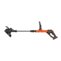
Speed Control Switch (Fig.A, H, P)
This string trimmer gives you the choice to operate at a
more efficient speed to extend the runtime for larger jobs, or
accelerate the trimmer speed for high-performancecutting.
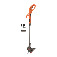
Attaching the Auxiliary Handle (Fig. D–F)
For some models the auxiliary handle
5
may need to be
attached. If the model needs the auxiliary handle attached,
please refer to theseinstructions.
1. To attach the auxiliary handle, press in on the auxiliary
handle adjustment buttons
24
on both sides of the
upperhousing.
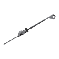
Replacing Guard (Fig.A–C)
WARNING: Never operate appliance
without guard firmly in place. Damage or personal injury
couldresult.
Remove CurrentGuard
1. Remove the guard screw
15
as shown in Fig.C.
2. Slide the guard
10
off.
Assembling the New Guard
1. Slide the guard into place as shown in Fig.B.
2. Replace and securely tighten the guard screw
15
.
Switching Trimmer On and Off (Fig.A)
WARNING: Never attempt to lock the
trigger in the onposition.
1. To turn the appliance on, press the lock-off button
2
and then squeeze the trigger switch
1
. Once the unit is
running, you may release the lock-off button.
2. To turn the appliance off, release thetrigger.
Installing and Removing the Battery Pack (Fig.H)
WARNING: Ensure the tool/appliance is
in the off position before inserting the batterypack.
NOTE: For best results, make sure your battery pack is
fullycharged.
1. To install the battery pack
12
into the tool handle, align
the battery pack with the rails inside the tool’s handle and
slide it into the handle until the battery pack is firmly seated
in the tool and ensure that it does notdisengage.
2. To remove the battery pack from the tool, press the
battery release button
13
and firmly pull the battery pack
out of the tool handle. Insert it into the charger.
OPERATION
WARNING: To reduce the risk of
serious personal injury, turn unit off and remove
the battery pack before making any adjustments or
removing/installing attachments or accessories, when
replacing line, or prior to cleaning. An accidental start‑up
can causeinjury.
Installing the Guard (Fig.A–C)
WARNING: Never remove the guard.
Damage or personal injury couldresult.
WARNING: NEVER OPERATE
APPLIANCE WITHOUT GUARD FIRMLY IN PLACE. The
guard must always be properly attached on the appliance to
protect theuser.
1. Remove the guard screw
15
.
2. Slide the guard
10
fully onto the motor housing
8
.
Make sure the tabs
18
on the guard engage the ribs
14
on
the trimmerhead.
3. Continue to slide the guard on until it “snaps” into place.
The locking tab
17
should snap into the housingslot
16
.
4. Using a crosshead screwdriver, insert the guard
screw
15
and tightensecurely.
5. Once the guard is installed, remove the covering from
the line cut-off blade, located on the edge of theguard.
ASSEMBLY AND ADJUSTMENTS
WARNING: To reduce the risk of
serious personal injury, turn unit off and remove
the battery pack before making any adjustments or
removing/installing attachments or accessories, when
replacing line, or prior to cleaning. An accidental start‑up
can causeinjury.
or AC/DC .... alternating or
direct current
...................... Class II
Construction
(double insulated)
n
o
.......................no load speed
n .........................rated speed
PSI....................... pounds per square
inch
......................earthing terminal
.....................safety alert symbol
..................... visible radiation–
do not stare into
the light
..................... wear respiratory
protection
..................... wear eye
protection
..................... wear hearing
protection
..................... r
ead all
documentation
.....................
do not expose to
rain
Releasing the Cutting Line (Fig.A)
In transit, the cutting line is taped to the spool housing
11
.
• Remove the tape holding the cutting line to the
spoolhousing.
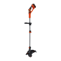
Height Adjustment (Fig.A, G)
CAUTION: Adjust the length of the trimmer
to obtain proper workingpositions.
1. The overall height of the trimmer can be adjusted by
loosening the height-adjust collar
6
by rotating it in the
direction of the arrow shown in Figure A, G.
2. Move the upper housing straight up or down. When the
desired height is achieved, tighten the collar by rotating it
opposite of the direction shown in FigureA, G.
2. Position the auxiliary handle as shown in Fig. D–F.
Partially push the auxiliary handle on so it will hold the
buttons in when you release them with your hand.
3. Push the auxiliary handle completely onto the housing
and position it slightly until it “snaps” intoplace.
NOTE: To adjust the auxiliary handle up or down, press in
on the buttons and raise or lower the handle.
NOTE: The handle should be adjusted so that your front
arm is straight when the tool is in the workingposition.
 Loading...