67
APPENDIX A: Quick Start Guide
This Guide shows you the basics of how to install and operate the ASD-4 in a
single-line, single-phone system. Please refer to Chapters 3 through 5 of this
manual for more information on this and other system configurations.
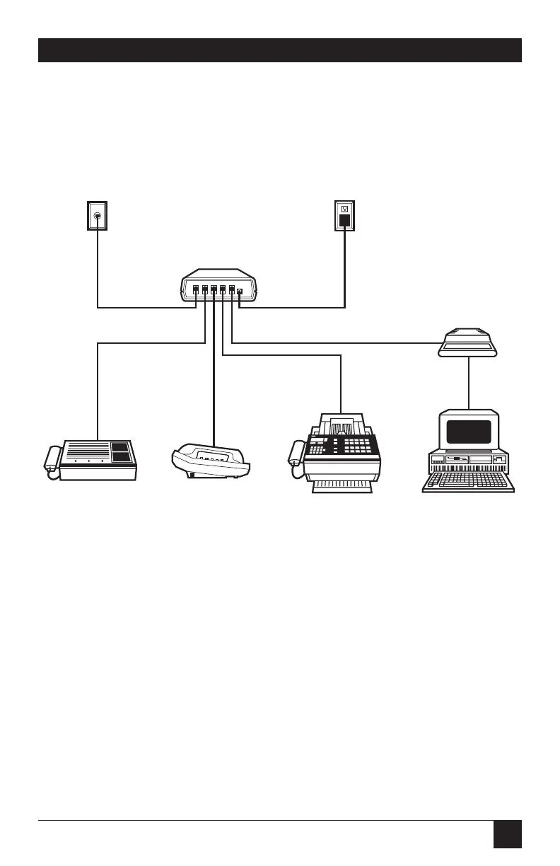
A.1 Installing the ASD-4
❶ Connect the incoming telephone line to the leftmost RJ-11 port (labeled
“LINE-IN”) on the ASD-4’s rear panel.
❷ Connect your answering machine to the second-from-left (“TAD”) port.
❸ Connect your phone to the middle (“PHONE”) port.
❹ Connect your fax or fax/modem to the second-from-right (“FAX”) port.
❺ Connect your modem to the rightmost (“MODEM”) RJ-11 port, and set the
modem to auto-answer on the first ring.
❻ Plug the cord of the ASD-4’s power supply into the jack labeled “12 VAC.”
Plug the power supply’s transformer into a wall outlet.
Appendix A: Quick Start Guide
❶
SINGLE
TELEPHONE
LINE
ANSWERING
MACHINE
FAX MACHINE
or FAX/MODEM
CARD
MODEM or
MODEM CARD
POWER
SUPPLY
TELEPHONE
PC
❷
❸
❹
❺
❻
ASD-4