EasyManua.ls Logo

Black Box LBLP01A-KIT User Manual

Black Box LBLP01A-KIT
13 pages
To Next Page IconTo Next Page
Page #1 background imageLoading...
Page #1 background image
BL A C K B OX
®
Extend Ethernet with 100-/60-Mbps downstream/
upstream connections over copper.
Bridges 10BASE-T/100BASE-TX Ethernet interface.
Supports connections up to 1000 feet (304.8 m).
Select from Fast and Interleaved modes.
Provides low latency for video/voice/data applications.
Conforms to Safety-Extra-Low-Voltage (SELV) standard.
VDSL2 Line Power Ethernet Extender Kit
Order toll-free in the U.S.: Call 877-877-BBOX (outside U.S. call 724-746-5500) •
FREE technical support 24 hours a day, 7 days a week: Call 724-746-5500 or fax 724-746-0746 •
Mailing address: Black Box Corporation, 1000 Park Drive, Lawrence, PA 15055-1018 •
Web site: www.blackbox.com • E-mail: info@blackbox.com
Customer
Support
Information
December 2009
LBLP01A-KIT
Question and Answer IconNeed help?

Do you have a question about the Black Box LBLP01A-KIT and is the answer not in the manual?

Black Box LBLP01A-KIT Specifications

General IconGeneral
CategoryExtender
ModelLBLP01A-KIT
BrandBlack Box
TypeHDMI Extender
Data Rate10.2 Gbps
Power5V DC
Power Supply5VDC
ConnectorsHDMI
Connector TypeHDMI, RJ45

Summary

Product Specifications

Performance Metrics

Details data rates, transmission distances, flow control, and MDI-X.

Regulatory Compliance

Lists the various industry standards the device complies with.

Physical & Environmental Details

Covers connectors, indicators, power input, and environmental tolerances.

Product Overview

Introduction to the Extender Kit

Provides an overview and introduction to the VDSL2 Ethernet Extender Kit.

Key Product Features

Lists the key features and capabilities of the VDSL2 Ethernet Extender Kit.

Application Scenario

Shows a typical network application diagram for the extender kit.

Package Contents

Itemizes the contents of the VDSL2 Line Power Ethernet Extender Kit package.

LED Indicator Guide

Details the function of each LED indicator on the master and slave units.

Unit Panel Layout

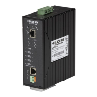
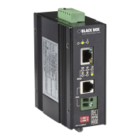
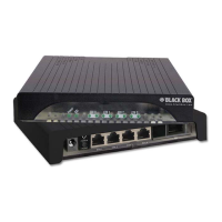
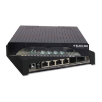
Describes the front and back panel components of the master and slave units.

Installation Guide

Installation Procedure

Provides sequential instructions for installing the Ethernet extender units.

Transmission Performance Table

Table showing data rates vs. transmission distances for the kit.

DIP Switch Configuration

DIP Switch Functionality Overview

Explains the purpose of each DIP switch for device configuration.

SW-1: CO/Remote Setting

Sets the unit mode to Central Office (Master) or Remote (Slave).

SW-2: Noise Protection Mode

Selects between Interleaved and Fast modes for impulse noise protection.

SW-3: Data Rate Limiting

Controls the maximum data rate of the line connection.

SW-4: SNR Margin Adjustment

Adjusts the SNR margin for link stability and error reduction.

Related product manuals