ENGLISH
BLACKSTONEPRODUCTS.COM/SUPPORT
OWNER’S MANUAL | ASSEMBLY GUIDE
ASSEMBLY INSTRUCTIONS
Find a large, clean area to assemble your appliance.
Remove all packing material before assembling.
CAUTION
Sharp edges. Wear gloves while assembling.
ELECTRIC REQUIREMENTS:
120V 60Hz
CAUTION
Heavy pieces. Two people should assemble this appliance.
NOTICE
Place appliance on a heat-resistant and flame-resistant
surface while in use.
NOTICE
DO NOT leave the hood closed for more than 10 minutes while
cooking.
NOTICE
• DO NOT mix old and new batteries.
• DO NOT mix alkaline, standard (carbon-zinc) or rechargeable
(ni-cad, ni-mh, etc.) batteries.
TOOLS NEEDED:
Phillips head screwdriver &
Adjustable wrench
TOOL NEEDED:
Phillips head screwdriver
TOOL NEEDED:
Adjustable wrench
TOOL NEEDED:
5mm Allen wrench
NOT INCLUDED:
LPG cylinder
Size: 18 x 12 in (45 x 30 cm), 20 lb (9 kg)
Size: 18 x 12 in (45 x 30 cm), 20 lb (9 kg)
LPG cylinder must include collar to
LPG cylinder must include collar to
protect LPG cylinder valve.
protect LPG cylinder valve.
NOT INCLUDED:
17" griddle base
NOT INCLUDED:
22" griddle base
NOT INCLUDED:
AA battery
NOT INCLUDED:
LPG cylinder
Size: 4 x 8 in (10 x 20 cm), 1 lb (453 g)Size: 4 x 8 in (10 x 20 cm), 1 lb (453 g)
NOT INCLUDED:
AAA battery
TOOLS NEEDED:
Phillips head screwdriver &
Adjustable wrench
TOOL NEEDED:
Phillips head screwdriver
TOOL NEEDED:
Adjustable wrench
TOOL NEEDED:
5mm Allen wrench
NOT INCLUDED:
LPG cylinder
Size: 18 x 12 in (45 x 30 cm), 20 lb (9 kg)Size: 18 x 12 in (45 x 30 cm), 20 lb (9 kg)
LPG cylinder must include collar to LPG cylinder must include collar to
protect LPG cylinder valve. protect LPG cylinder valve.
NOT INCLUDED:
17" griddle base
NOT INCLUDED:
22" griddle base
NOT INCLUDED:
AA battery
NOT INCLUDED:
LPG cylinder
Size: 4 x 8 in (10 x 20 cm), 1 lb (453 g)Size: 4 x 8 in (10 x 20 cm), 1 lb (453 g)
NOT INCLUDED:
AAA battery
MODEL:
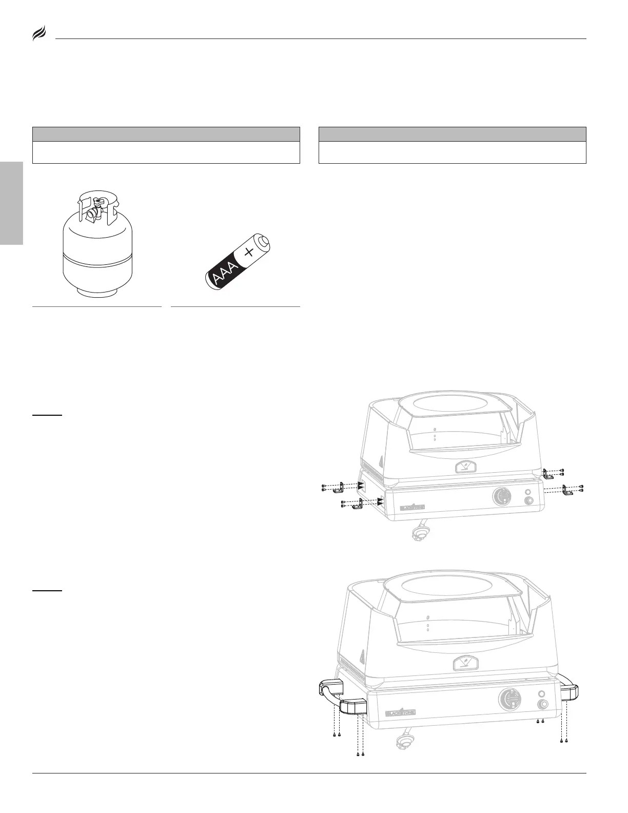
STEP 02
Slide one (1) handle stando (L) and one (1) handle stando
(R) onto one (1) side handle.
Use four (4) M6x12 screws [a.] to attach the handle to the fixing
plates on the left side of the burner box.
Repeat with the other handle.
STEP 01
Place the oven base on a smooth flat surface.
Use eight (8) M6x12 screws [a.] to attach four (4) fixing plates to the
burner box.
L
R
L
R


 To Next Page