EasyManua.ls Logo

blackburn Delphi User Manual

blackburn Delphi
24 pages
To Next Page IconTo Next Page
Page #1 background imageLoading...
Page #1 background image
TABLE OF CONTENTS TABLE OF CONTENTS
ENGLISH
ENGLISH
Introduction 1
Warnings and Cautions 2
Care and Maintenance 3
Parts of your Blackburn Delphi Cycle Computer 4
Resetting the Computer to its Default Settings 5
Shipping and Sleep Modes 6
Changing the Battery in the Blackburn Delphi Cycle Computer 7
Installing the Computer on your Bike 9
Keys and their Functions 15
Sections of LCD Display 18
Basic Operation 23
Bike One/Bike Two Setting 27
Program Wheel Size, Units and Chronograph 28
Program Odometers 36
Program Time of Day 38
Operating the Ride Time and Total Time Chronographs 41
Starting Stopping and Clearing the Chronograph and Memory 42
Clearing Maximum Speed or Maximum Cadence Only 43
Technical Data 44
Warranty and Repair 46
Blackburn_2/3_Manual 8/3/05 10:00 AM Page 2
Question and Answer IconNeed help?

Do you have a question about the blackburn Delphi and is the answer not in the manual?

blackburn Delphi Specifications

General IconGeneral
DisplayLCD
BatteryCR2032
AltimeterNo
Heart RateNo
CadenceNo
Mount TypeHandlebar
MaterialPlastic
FoldableNo
LockableNo
TypeBike Computer
FunctionsSpeed, Distance

Summary

Introduction

Warnings and Cautions

Care and Maintenance

Parts of Your Blackburn Delphi Cycle Computer

Face of Computer

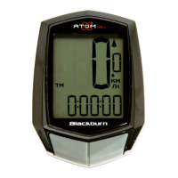
Identifies the main display unit.

Wheel Magnet

Component for detecting wheel rotation.

Zip-Ties

Fastening accessories.

Wired Speed Bracket

Mount for the speed sensor.

Wired Speed & Cadence Bracket with Cadence Sensor

Bracket for both speed and cadence sensors.

Bracket Sleeve

Component for handlebar mounting.

Resetting the Computer to its Default Settings

Shipping and Sleep Modes

Shipping Mode

Computer state for shipping and storage.

Sleep Mode

Power saving mode when inactive.

Changing the Battery in the Blackburn Delphi Cycle Computer

Replacing the Computer Battery

Step-by-step guide for battery replacement.

Installing the Computer on Your Bike

Installing Wired Front Wheel Speed Sensor and Bracket

Instructions for mounting the front wheel speed sensor.

Installing Wired Rear Wheel Speed and Cadence Sensors and Bracket

Guide for installing rear wheel speed and cadence sensors.

Installing Wired Rear Wheel Speed and Cadence Sensors and Bracket (Continued)

Continuation of rear sensor installation procedures.

Attaching the Computer Head to the Handlebar Bracket and Testing

Mounting the computer unit and verifying its function.

Keys and Their Functions

Quick Press vs. Press & Hold

Explains different key press methods for operation.

Upper Display/EL Key

Details the function of the upper display key.

Option Key

Details the function of the option key.

Start/Stop Key

Details the function of the start/stop key.

Mode Key

Details the function of the mode key.

Sections of LCD Display

Speed Window

Area on the LCD display showing current speed.

KM/H and M/H

Indicators for unit settings in Miles/Kilometers.

Upper Data Window

Details the upper data display area of the LCD.

CAD

Icon indicating that cadence is displayed.

Chronograph Window

Area on the LCD display for chronograph information.

Comparison Arrows

Indicators for current speed relative to average speed.

RT/TT

Icons indicating Ride Time or Total Time chronograph.

Lower Data Window

Details the lower data display area of the LCD.

Bike 1/Bike 2

Icons indicating the selected bike profile.

AM

Indicator for AM time on the 12-hour clock.

Basic Operation

Mode and Option Flow Sequences

Diagram showing navigation through data displays.

Upper Data Window Flow Sequences

Diagram showing options for the upper data window.

Step by Step-Changing the Upper Data Window Information

Guide to changing the content displayed in the upper window.

Bike One/Bike Two Setting

Change Bike I/Bike 2 Setting

Procedure to switch between bike profiles.

Program Wheel Size, Units and Chronograph

Preset Wheel Sizes

List of pre-programmed wheel/tire sizes.

Measured Wheel Size

Options for accurately measuring wheel circumference.

Measuring Wheel Size Using Radius Method

Method to measure wheel circumference using its radius.

Measuring Wheel Size Using Rollout Method

Method to measure wheel circumference by rolling.

Step by Step-Enter a Pre-Programmed Wheel Size

Guide to selecting a wheel size from the preset list.

Step by Step-Enter an Exact Wheel Size

Guide to manually entering a specific wheel size.

Step by Step-Set Speed and Distance Units

Procedure to set speed and distance units (M/H or KM/H).

Step by Step-Set Chronograph Function

Setting the chronograph to display Ride Time or Total Time.

Program Odometers

Step by Step-Setting the Programmable Odometers

Guide to setting initial odometer values for bikes.

Program Time of Day

Step by Step-Setting the Time of Day

Guide to setting the clock and its 12/24 hour format.

Operating the Ride Time and Total Time Chronographs

Starting Stopping and Clearing the Chronograph and Memory

Starting and Stopping the Ride Time Chronograph

How the ride time chronograph starts and stops automatically.

Starting and Stopping the Total Time Chronograph

How the total time chronograph starts and stops manually.

Clearing All Ride Data

Procedure to reset all stored data and memory values.

Technical Data

Clearing Maximum Speed or Maximum Cadence Only

Resets maximum speed and cadence values independently.

Functions and Operational Ranges (Continued)

Continued list of device functions and operational ranges.

Related product manuals