EasyManua.ls Logo

BLACKMER XL2B - User Manual

BLACKMER XL2B
16 pages
Print Icon
To Next Page IconTo Next Page
Loading...
BLACKMER POWER PUMPS
960260
INSTRUCTIONS NO. 107-B00
INSTALLATION OPERATION AND MAINTENANCE INSTRUCTIONS
Section
Effective
Replaces
107
Jul 2018
Jan 2014
MODELS: XL2B, XL3B, XL4C
TABLE OF CONTENTS Page
PUMP DATA
Technical Data 2
Initial Pump Start Up Information 2
INSTALLATION
Pre-Installation Cleaning 3
Location and Piping 3
Mounting 3
Coupling Alignment 3
Pump Rotation 4
To Change Pump Rotation 4
Check Valves 4
OPERATION
Pre-Start Up Check List 4
Start Up Procedures 5
Running the Pump in Reverse Rotation 6
Flushing the Pump 6
Pump Relief Valve 6
Relief Valve Setting and Adjustment 6
MAINTENANCE
Lubrication 7
Strainers 7
Vane Replacement 8
Pump Disassembly 8
Parts Replacement 8
Pump Assembly 9
FLANGE MOUNTED GEAR REDUCER MAIN. 12
TROUBLE SHOOTING 14
NOTE: Numbers in parentheses following individual parts
indicate reference numbers on Blackmer Parts Lists.
Blackmer pump manuals and parts lists may be obtained
from Blackmer's website (www.blackmer.com) or by
contacting Blackmer Customer Service.
Pump Parts Lists
2 and 3 - inch 4 - inch
107-B01 107-B02
SAFETY DATA
This is a SAFETY ALERT SYMBOL.
When you see this symbol on the product, or in the
manual, look for one of the following signal words and be
alert to the potential for personal injury, death or major
property damage
Warns of hazards that WILL cause serious personal injury,
death or major property damage.
Warns of hazards that CAN cause serious personal injury,
death or major property damage.
Warns of hazards that CAN cause personal injury
or property damage.
NOTICE:
Indicates special instructions which are very
important and must be followed.
NOTICE:
Blackmer Pumps MUST only be installed in systems,
which have been designed by qualified engineering
personnel. The system MUST conform to all applicable
local and national regulations and safety standards.
This manual is intended to assist in the installation and
operation of the Blackmer power pumps, and MUST be
kept with the pump.
Pump service shall be performed by qualified technicians
ONLY. Service shall conform to all applicable local and
national regulations and safety standards.
Thoroughly review this manual, all instructions and hazard
warnings, BEFORE performing any work on the pump.
Maintain ALL system and pump operation and hazard
warning decals.
Question and Answer IconNeed help?

Do you have a question about the BLACKMER XL2B and is the answer not in the manual?

Overview

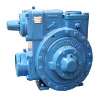
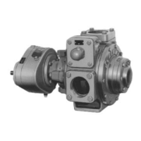
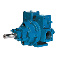
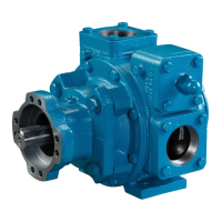
The Blackmer Power Pumps, specifically models XL2B, XL3B, and XL4C, are positive displacement pumps designed for various industrial applications. This manual provides comprehensive instructions for their installation, operation, and maintenance, emphasizing safety and proper procedures to ensure optimal performance and longevity.

Function Description

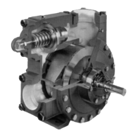
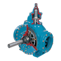
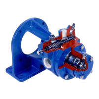
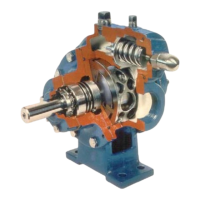
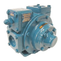
Blackmer Power Pumps are rotary vane pumps, a type of positive displacement pump. They operate by trapping a fixed volume of fluid between vanes and a rotor, then moving that fluid from the inlet to the outlet. This design allows them to handle a wide range of viscosities and provides consistent flow rates, even against varying discharge pressures. The internal relief valve, a key feature, protects the pump from excessive pressure by bypassing fluid back to the suction side. However, it's crucial to note that this internal relief valve is designed for pump protection, not as a system pressure control valve, especially for extended periods or with volatile liquids that might cause cavitation. For such applications, an external system pressure control valve with bypass piping back to the storage tank is recommended. The pumps are capable of self-priming, which simplifies start-up in many scenarios. They can also be operated in reverse rotation for limited periods for system maintenance, though at a reduced performance level and only with an external pressure relief valve in place.

Important Technical Specifications

The manual provides key technical data for both 2, 3-inch and 4-inch models:

  • Maximum Pump Speed:
    • 2, 3-inch models: 780 RPM
    • 4-inch models: 640 RPM
  • Maximum Operating Temperature: 240°F (115°C) (for standard materials of construction)
  • Maximum Differential Pressure: 150 psi (10.3 Bar)
  • Maximum Working Pressure: 350 psi (24.1 Bar)

These specifications highlight the operational limits and capabilities of the pumps. For specific material requirements or optional constructions, consulting Blackmer Material Specs is advised.

Usage Features

  • Installation: Proper installation is critical for pump life and performance. The manual stresses the importance of a solid foundation to reduce noise and vibration, and recommends securing the unit with anchor bolts. Piping should be designed to minimize inlet pipe friction, with the inlet line at least as large as the intake port and sloping downward to the pump. A strainer is recommended in the inlet line to protect against foreign matter, located at least 24" (0.6m) from the pump, and cleaned regularly. Air leaks in the intake system must be avoided. For units with a flange-mounted gear reducer, no coupling alignment is required as the motor, gearbox, and pump are rigidly connected. However, shimming may be necessary to reduce stress. For long-coupled units, precise angular and parallel coupling alignment using a laser alignment tool or dial indicator is essential, with maximum offsets of .005" (.127 mm).
  • Pre-Installation Cleaning: New pumps contain residual test fluid and rust inhibitor, which may require flushing prior to use. The supply tank and intake piping must also be thoroughly cleaned and flushed to prevent foreign matter from entering the pump and causing damage.
  • Pump Rotation: Pumps are available in right-hand (clockwise) or left-hand (counterclockwise) configurations, with the intake on the respective side when viewed from the driven end. Reversing pump rotation requires disassembly and reassembly with the shaft on the opposite side.
  • Check Valves: The use of check valves or foot valves in the supply tank is not recommended with self-priming, positive displacement pumps. However, a check valve in the discharge piping is recommended to prevent liquid backflow and reverse rotation when the pump is off, which could cause undue stress.
  • Start-Up Procedures: Before starting, a pre-start-up checklist ensures proper pipe alignment, coupling alignment (if applicable), and correct oil levels for gearboxes. The entire pumping system, including valves, must be verified as open or closed as appropriate. Pressure gauges should be installed to monitor suction and discharge conditions. The motor wiring should be checked, and power briefly turned on to confirm correct rotation. Priming should occur within one minute of starting. After start-up, checks for leakage, overheating, noise, vibration, and flow rate are essential. The relief valve pressure setting must be checked by briefly closing a discharge line valve and reading the pressure gauge, ensuring it is 15-20 psi (1.0-1.4 bar) higher than the maximum operating pressure. The pump should not run with a completely closed discharge valve for more than 10-15 seconds.
  • Flushing: For system maintenance, the pump can be flushed with a compatible, lubricating, non-corrosive fluid. This involves running the pump with the discharge valve open and intake valve closed, bleeding air, and then running flushing fluid through. Residual fluid will remain, and proper disposal of waste fluids is mandated.
  • Relief Valve Adjustment: The relief valve setting is marked on a metal tag. Adjustments to increase or decrease pressure involve removing the cap, loosening the locknut, and turning the adjusting screw inward (clockwise) or outward (counterclockwise). It is critical NOT to remove the relief valve cap or adjust the setting while the pump is in operation, as incorrect settings can lead to pump component failure, personal injury, and property damage.

Maintenance Features

  • Scheduled Maintenance:
    • Lubrication: Pump bearings require lubrication every one to twelve weeks, depending on the application. Recommended greases include Mobilgrease XHP222 and RONNEX MP Grease. The greasing procedure involves removing grease relief fittings, slowly applying grease until it escapes, and then replacing the fittings. Overgreasing should be avoided. For Blackmer gear reducers (if supplied), they are shipped without oil and must be filled with the specified grade. The oil should be changed after the first 48 hours of use and approximately every 500 hours thereafter.
    • Strainers: Strainers must be cleaned regularly to prevent pump starvation, with frequency depending on the application.
  • Vane Replacement: This procedure involves flushing the pump, relieving pressure, removing the outboard head assembly, and then replacing vanes one by one, ensuring the rounded edge is up and relief grooves face the direction of rotation.
  • Pump Disassembly and Assembly: Detailed instructions are provided for disassembling the pump, starting from the inboard (driven) end, to remove bearing covers, locknuts, head assembly, rotor, shaft, and liner. During reassembly, all components should be inspected for wear and damage, and O-rings replaced. Special attention is given to installing the mechanical seal components, ensuring proper orientation of the disc relief hole, and correctly adjusting the bearing locknuts to prevent binding or excessive play.
  • Flange Mounted Gear Reducer Maintenance: For units equipped with NORD gear reducers, detailed maintenance instructions are available on the NORD website. Excerpts in the manual cover storage (short-term and long-term) and commissioning. Long-term storage requires specific precautions like filling the reducer with oil, applying grease to exposed surfaces, and periodic shaft rotation to prevent brinelling and seal drying. Commissioning after storage involves checking for a vent, ensuring proper lubricant type and level, inspecting seals, and removing anti-corrosive protectant.
  • Troubleshooting: A comprehensive troubleshooting guide addresses common issues such as leakage (between head & casing, around shaft), shaft binding, overheating, low delivery rate, excessive noise and vibration, poor or no priming, and damaged vanes. For each problem, probable causes and corrective actions are listed, ranging from inspecting O-rings and cleaning components to adjusting relief valves and checking piping. For example, shaft binding can be caused by burrs, dirt, improper locknut adjustment, or contaminated mechanical seal faces, with corrective actions including cleaning, proper adjustment, and lubrication. Low delivery rate can stem from a low relief valve setting, restrictions in the suction or discharge lines, air leaks, or worn pump parts. Excessive noise and vibration may indicate cavitation, worn components, or misalignment. Damaged vanes can result from foreign objects, running dry, cavitation, high viscosity, or incompatibility with pumped liquids. Broken shafts can be caused by foreign objects, high viscosity, relief valve not opening, hydraulic hammer, or misalignment. Seal leakage can be due to incompatible O-rings, nicks, cuts, twists, shaft damage, excessive cavitation, or cracked seal faces. Motor overload can be caused by insufficient motor horsepower, improper wiring, misalignment, or incorrect bearing locknut adjustment.

Throughout the manual, safety is paramount, with numerous warnings (DANGER, WARNING, CAUTION) and notices highlighting potential hazards such as serious personal injury, death, major property damage, electrical shock, burns, and the risks associated with hazardous fluids or operating without guards. Maintenance is strictly to be performed by qualified technicians following all procedures and warnings.

BLACKMER XL2B Specifications

General IconGeneral
BrandBLACKMER
ModelXL2B
CategoryPower Pump
LanguageEnglish

Related product manuals