ENGLISH
4
SAVE THESE
INSTRUCTIONS FOR
FUTURE USE
COMPONENTS (FIG. A)
WARNING: Never modify the power tool or any part
of it. Damage or personal injury couldresult.
Refer to Figure A at the beginning of this manual for a
complete list ofcomponents.
INTENDED USE
This appliance is designed for household outdoor
blowerapplications.
DO NOT use under wet conditions or in presence of
flammable liquids orgases.
DO NOT let children come into contact with the tool.
Supervision is required when inexperienced operators use
thistool.
ASSEMBLY AND ADJUSTMENTS
WARNING: To reduce the risk of serious personal
injury, turn unit off and unplug before making
any adjustments or removing/installing
attachments or accessories. An accidental start-up
can causeinjury.
WARNING: Before attempting any of the assembly
steps below, ensure product is switched off and
disconnected from the powersupply.
ASSEMBLY FOR BLOW MODE
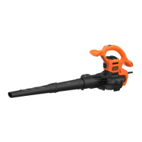
Blow Tube Assembly (Fig. C–E)
• Fit fan cover
14
as shown in Fig. C until audible click
isheard.
CAUTION: CUT HAZARD. Ensure fan cover
14
is
securely seated and latched intoposition.
NOTE: Unit will not operate in blow mode without fan
cover inplace.
• Align the upper
9
and lower tubes
10
as shown in
Fig.C.
• Push the lower tube firmly into the upper tube, until the
tubes click intoplace.
Fig. C
9
10
• Blow tubes must be assembled to the power head
beforeuse.
• Never operate without both lower and upper
tubesassembled.
• In the interest of safety, it is not intended for the tubes to be
separated onceassembled.
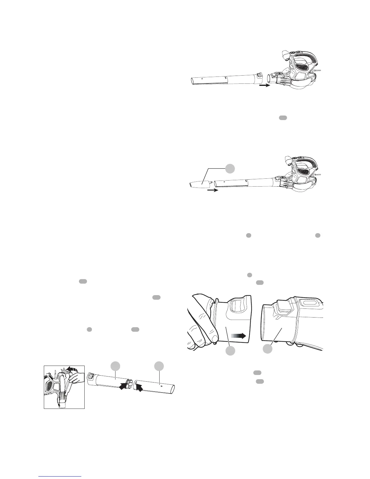
• Push the tube assembly onto the power head until it
is in the fully locked in position and an audible click is
heard. (Fig. D).
Fig. D
CAUTION: CUT HAZARD. Ensure the tube assembly is
securely seated and latched intoposition.
• Use the air concentrator attachment
11
to target
air flow to a tighter area. Add the attachment to the
assembly as shown in Fig. E. Push on until hole in tab
engages raised post ontube.
Fig. E
11
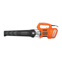
ASSEMBLY FOR VACUUM MODE
Attaching Flexible tube to Power head
(Fig. F, Q)
1. Align the power head
1
and flexible collection tube
7
as shown in Fig.F.
2. Push the flexible collection tube assembly onto the
power head until it is in the fully locked position and an
audible click is heard. (Fig. F).
3. Seal the collection bag
8
, roll the open end of the bag
and latch the retaining clip
17
closed as shown in Fig.Q.
Fig. F
1
7
Adjusting harness (Fig. G)
1. Place the shoulder straps
15
over yourshoulders.
2. Pull the adjustment straps
16
down until the backplate
is firm against your back as shown in Fig.G.