10
ENGLISH
(Original instructions)
Do not expose the appliance to rain or high
humidity.
Disconnect the mains plug if the cord becomes
damaged or entangled.
Electrical safety
#
This tool is double insulated; therefore no
earth wire is required. Always check that the
power supply corresponds to the voltage on
the rating plate.
u If the supply cord is damaged, it must be replaced by the
manufacturer or an authorised Stanley FatMax Service
Centre in order to avoid a hazard.
Voltage drops
Inrush currents cause short-time voltage drops. Under unfa-
vourable power supply conditions, other equipment may be
affected. If the system impedance of the power supply is lower
than 0.361, disturbances are unlikely to occur.
Using an extension cable
Always use an approved extension cable suitable for the
power input of this tool (see technical data). Before use,
inspect the extension cable for signs of damage, wear and
ageing. Replace the extension cable if damaged or defective.
When using a cable reel, always unwind the cable completely.
Use of an extension cable not suitable for the power input of
the tool or which is damaged or defective may result in a risk
of re and electric shock.
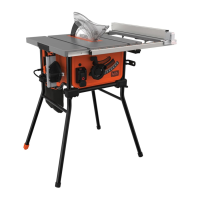
Features
This tool includes some or all of the following features.
1. Saw table
2. Blade guard
2a. Blade guard storage
3. Riving knife
4. Saw blade
4a. Saw blade storage
5. Rip fence
5a. Rip fence storage
6. Mitre gauge
6a. Mitre gauge storage
7. Dust bag
8. On/off switch
9. Leg stand
10. Bevel adjustment locking knob
11. Blade elevation handle
12. Leg stand locking knob
13. Blade tilting wheel
14. Locking handle for extension table
15. Locking handle for rip fence
16. Extension table
17. Spanner wrench X2
18. Guide rail
19. Push stick
20. Table insert
21. Overloaded protector
22. Leg stand level adjustor
23. Power cable
24. Power cable storage tabs
Assembly
uOpen the box and lift the saw out.
u Place the saw on a smooth, at surface such as a
workbench or strong table.
Assembling the leg stand (Fig. A, B & C)
Note: The leg stands have been designed so they can only
be assembled one way. ensure that the legs always slope
outwards as shown on front cover and assembly drawing on
page 2.
uUnscrew and remove all four leg stand locking knobs (12)
as shown in gure A.
uPlace the table saw upside down on a stable surface,
and insert the leg stands (9) as shown in gure B. Ensure
correct orientation.
uReplace the leg stand locking knobs (12) ensuring they
pass through the holes on the leg stands (9) and tighten
securely, as shown in gure B.
uThe table saw comes with a leg stand level adjustor (22),
this can be adjusted to compensate for irregular oors, as
shown in gure C.
Riving knife set-up (Fig. D, E & F)
Warning! For transport reasons, the riving knife (3) has been
xed in the lower position before initial commissioning. Only
work with the machine if the riving knife (3) is in the upper
position. Fitting the riving knife (3) in the upper position
is as follows:
uRemove the securing screw (20a) on the table insert (20)
and lift the table insert clear from the saw, as shown in
gure D.
uRaise the saw blade and riving knife assembly by turning
the blade elevation handle (11) anti clockwise, as shown
in gure E.
uLoosen the locking handle (3a) and pull the riving knife (3)
into the upper position, as shown in gure F.
uReturn the locking handle (3a) to the locked position.
Blade guard assembly (Fig. G)
uThe blade guard (2) is supplied with a pre-assembled bolt
(2a) xed into the correct position.