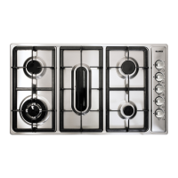
This document provides comprehensive instructions for the use, installation, and maintenance of a Blanco Built-In Hot Plate, specifically the Model BCG95, a 90 cm, 5-burner gas cooktop with side controls.
Function Description:
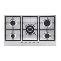
The Blanco BCG95 is a gas cooking appliance designed for domestic use, offering five burners for various cooking needs. It is built to blend seamlessly with modern kitchen décor, emphasizing ease of use and high performance. The cooktop is designed to be installed as a built-in unit in a kitchen countertop.
Important Technical Specifications:
- Model: BCG95
- Type: 90 cm, 5-burner gas cooktop (side control)
- Burner Types and Power Ratings (Natural Gas / U-LPG):
- Ultra rapid gas burner/Wok: 15.0 MJ / 15.0* MJ (13.0 MJ for models with enamelled steel trivets)
- Rapid gas burner: 12.0 MJ / 11.5 MJ
- Semi-rapid gas burner: 7.3 MJ / 6.9 MJ
- Auxiliary gas burners: 4.0 MJ / 3.8 MJ
- Fish gas burner: 12.0 MJ / 11.5 MJ
- Pan Diameter Recommendations:
- Ultra rapid or Wok: 24-26 cm
- Rapid: 20-22 cm
- Semi-rapid: 16-18 cm
- Auxiliary: 10-14 cm
- Fish: 20 cm (width), 36 cm (length)
- Gas Connection: Located at the rear, 100 mm from the right-hand side. Can be connected with rigid pipe (AS5601 table 3.1) or a hose assembly (AS/ANZ 1869, 10mm ID, class B or D, max 1.2m long).
- Natural Gas Pressure: 1.00 kPa
- U-LPG Gas Pressure: 2.75 kPa
- Electrical Connection: Supplied with an 1800 mm long flexible supply lead. Point of attachment is at the rear, 380 mm from the right-hand side. The appliance must be earthed.
- Overall Dimensions: 860 x 500 mm
- Cut-out Dimensions (for installation): 833 x 475 mm
- Minimum Depth from Work Surface: 60 mm
- Ventilation: Must comply with AS 5601/AG 601 - Gas Installation. Requires adequate ventilation, natural air vents (minimum section 100 cm²), or mechanical aeration (suction hood or electric fan).
- Surrounding Surface Temperature: Wall and bench surfaces must withstand temperatures of 75°C.
- Clearances:
- Adjoining wall surface within 200 mm from hob edge: must be non-combustible for 150 mm height.
- Combustible construction above hotplate: at least 600 mm above burner top.
- No construction within 450 mm above burner top.
- Power Supply Cable: H05 RR - F, Section 3 X 0.75 mm² (Single-Phase Power Supply). The ground wire should be longer than the phase conductors.
Usage Features:
- Ignition Methods:
- Manual Ignition: Push and turn the knob to the full on position (large flame), then place a lighted match near the burner.
- Electrical Ignition: Push and turn the knob to the full on position, then depress and release the ignition button "E".
- Automatic Electrical Ignition: Push and turn the knob to the full on position, then depress the knob.
- Flame Failure Device: For burners equipped with this device, turn the knob to the full on position, depress it for about 10 seconds after ignition to ensure the flame remains lit.
- Burner Cap Placement: Ensure the flame divider (Burner Cap) is correctly placed before attempting to light a burner.
- Efficient Use:
- Use appropriate pan sizes for each burner (refer to the provided table).
- Reduce flame to the "reduced rate" position (small flame) once the pan comes to a boil.
- Always place a lid on pans to conserve energy.
- Control Knobs: Each knob corresponds to a specific burner, indicated by a screen-printed diagram on the front panel.
- "Reduced Rate" Adjustment (for Natural Gas only): Allows fine-tuning of the minimum flame setting using a small screwdriver. The screw must be fully locked for Liquid gas burners.
- Gas Type Conversion: The appliance can be converted between U-LPG and Natural Gas by replacing injectors and adjusting gas pressure and by-pass screws. Specific injector sizes are provided for each gas type.
Maintenance Features:
- Cleaning:
- Always disconnect from gas and electricity mains before cleaning.
- Regularly wash the hot plate, enamelled steel or cast iron pan support, enamelled burner caps ("A", "B", "C"), and burner heads ("T") with lukewarm soapy water. Rinse thoroughly and dry.
- Never wash while warm or use abrasive powders.
- Avoid prolonged contact of vinegar, coffee, milk, salted water, lemon, or tomato juice with enamelled surfaces.
- Do not use steam jets for cleaning.
- Preventative Maintenance:
- Clean up spills immediately.
- Keep burners clean and free of debris.
- Ensure electrode and thermocouples are clean.
- Re-assemble burners correctly.
- Avoid getting water near injectors.
- Burner Re-assembly:
- Check that burner head slots are not clogged.
- Ensure burner caps ("A", "B", "C") are correctly positioned and steady on the burner head.
- Pan supports should be positioned with rounded corners towards the side edge of the hot plate.
- Tap Maintenance:
- If a tap becomes stiff, it must be greased by an authorized technician. This involves removing the tap, cleaning the cone with solvent, lightly spreading grease, re-fitting, operating several times, and then re-checking for excess grease and clear gas ducts.
- Replace seal "D" whenever a tap is replaced to ensure tightness.
- Servicing:
- Servicing should only be carried out by authorized personnel.
- Always turn off electrical ignition before servicing.
- To replace hot plate parts, remove knobs, movable parts (trivets, burners, caps), and screws "V" on the burners.
- All seals must be replaced by the technician after adjustments.
- Warranty: Complete the warranty section of the manual and retain the receipt as proof of purchase. Faulty installation is not covered under warranty.
- Data Label: Located on the underside of the hotplate, with a duplicate supplied for an accessible area. Ensure the gas supply matches the Data Label.