TECHNICAL DATA
Table 1. Technical data of the unit
Parameters VENTO A50 / A50-1 / A50 S / A50-1 S
Supply Voltage / 50 Hz [V] 230
Speed 1 2
Total unit power [W] 3.68 4.83
Total unit current [A] 0.021 0.026
Max. air ow [m
3
/h] 26 53
Sound pressure level at 3 m distance [dBA] 24 34
Sound pressure level at 1 m distance [dBA] 14 24
Transported air temperature [°C] from -20 up to +50
Total ltering class of 2 lters G3
Heat regeneration eciency [%] up to 90
Regenerator type Ceramic energy accumulator
Ingress Protection Rating IP24
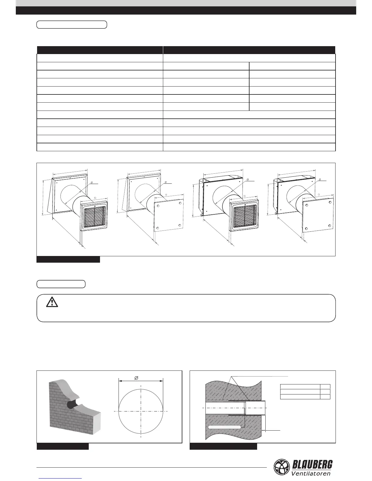
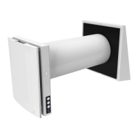
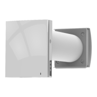
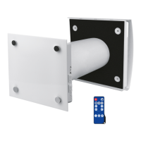
Fig. 6. Overall dimensions [mm]
Distance ring
А
Inside Outside
Model А, mm
VENTO A50 / A50-1 10
VENTO A50 S / A 50-1 S 10-110
Fill the gaps with a mounting foam
MOUNTING
WARNING
Read the operation manual prior to any electric installations. Connection of the unit to power mains is allowed by qualified professionals.
The unit is designed for through-the-wall mounting in the building outer
wall.
Mounting sequence:
1. Prepare a round core hole through the outer wall. The size is shown in the
gure 7. While mounting several connected in series units provide a recess
for the cable layout during the hole preparation to enable series connection
of several units.
2. Install the telescopic air duct in the wall. The protruding telescopic air duct
section on outer wall side must be equal to the distance A, g. 8.
3. Fill the gaps between the wall and the telescopic air duct with a mounting
foam.
Fig. 8. Telescopic air duct mounting
170
Fig. 7. Size of the core hole
212
240-460