Screws
Screws
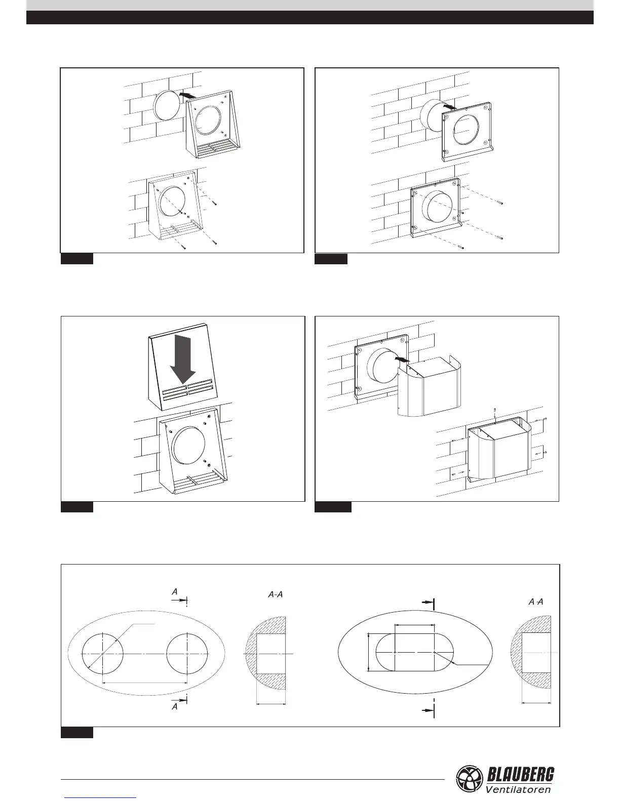
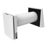
10. Fix the back part of the outer hood on the wall.
• Fig. 13a - models VENTO A50 / A50-1. Fix the back part of the outer ventilation
hood to the wall with the screws 4x40 from the delivery set.
• Fig. 13b -models VENTO A50 S / A50-1 S. Fix the back part of the outer
ventilation hood to the wall with the screws 4x40 from the delivery set.
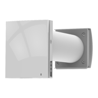
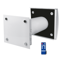
11. Install the upper part of the outer ventilation hood:
• Fig. 14a − for the model VENTO A50 / A50-1;
• Fig. 14b − for the model VENTO A50 S / A50-1 S.
Fig. 13а.
Fig. 14а.
Fig. 13b.
Fig. 14b.
12. Install the control panel SEA-T12 with a power unit inside a prepared hole
in the wall, see g. 15. The control panel mounting place must be inaccessible
for children. During selection of the control panel mounting place consider the
supplied cable length. A longer cable may be used if required, of Unitronic LIYY
UL CSA 5xAWG/7 (5x0.25) type.