Installation
.
Recommendations
l
Carefully choose the mounting location so that the unit won’t interfere with normal driving.
l
Avoid installing the unit in a place:
-
Subject to temperatures exceeding 55 degrees C (131 degrees
F)
(such as in a car parked in direct
sunlight.)
-
Subject to direct sunlight
-
Subject to excessive vibration
-
Near heat sources (such as heaters and heat ducts)
-
Exposed to rain, moisture, excessive dirt and/or dust
l
This unit should not be installed in any way except that which is authorized (on its side, on its end, at
_
a 45” angle or suspended). Installing it with its side facing down or upside down can cause
malfunctioning.
l
The fuel tank must not be damaged by the installation.
I.
l
The unit should not cover any wires or pipelines.
l
The unit (and its installation) should not damage or interfere with access to the spare tire, tools or
other equipment in or under the trunk.
l
For a safe and secure installation, be sure to use only the supplied mounting hardware.
l
Press the reset button after completing the electrical connections and installation. The reset button is
located on the front of the Commander (See page 5).
l
If you have any questions or problems concerning your unit that are not covered in this manual,
please contact your Blaupunkt dealer.
l
Be sure to remove the transport screws (See page 5).
>
Anti-Vibration Setting
l
This unit can be installed horizontally (to the floor or suspended), vertically, and at a 45” angle.
l
Once the installation position has been chosen, set Anti-Vibration Setting Switches on both sides of
the unit using a screwdriver.
l
The unit may skip if used with the wrong installation setting.
Type of Installation
Horizontal
Suspended
Vertical
45” angle
Setting
H
H
V
45”
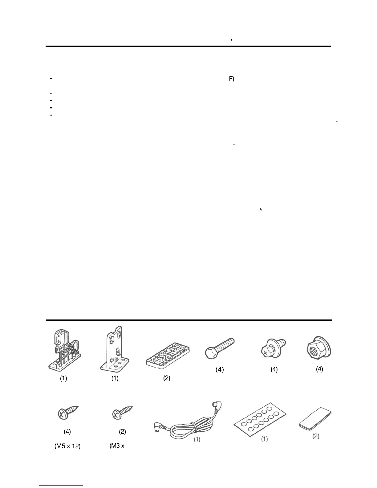
Mounting Hardware
(1)
Bracket (L)
(4)
Tapping Screw
(M5x12)
(1)
Bracket (R)
(2)
Bracket (B)
(4)
‘Hexagonal Bolt
(M6 x20)
(4)
Hexagonal Bolt
With Washer
(M5 x 8)
(4)
Nut
(M6)
(2)
Tapping Screw
(M3x
12)
DIN 8 Pin Cable
Seal
Double
Sided Tape
7