In conclusion,
allow
us
a
few
words
about
the
topic
of
health
protection: .
During
the
playback
of
music in
your
vehicle, please cons1der
that
continuous
sound-pressure
levels
above
1
00
dB can
lead
to
permanent
damages
to
the
human
ear and even
to
loss
of
hearing. Using today's
high-performance
systems
and loudspeaker
configurations
allows
for
reaching sound-
pressure
levels
above
130
dB.
Safety notes
Please
observe
the
following
safety notes
during
the
instal-
lation
and
connection.
Disconnect
the
negative
pole
of
the
battery!
Observe
the
safety notes
of
the
vehicle manufacturer.
- When
you
drill
holes, ensure
that
you
do
not
damage
any
vehicle
components.
- The cross section
of
the
plus
and
minus
cable
may
not
be
less
than
6
mm
2
•
- Use cable
glands
for
holes
with
sharp edges.
- An
incorrect
installation
can
result in
malfunctions
of
the
electronic
vehicle
systems
or
your
car
sound
system.
Installation
and connection instructions
With
respect
to
accident
safety,
the
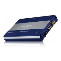
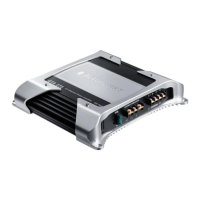
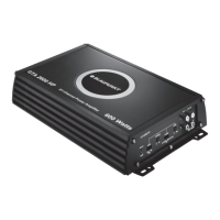
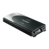
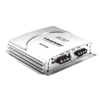
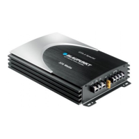
GTA
1500 D
must
be
secured in a professional way.
When selecting
the
installation
location,
select a
dry
location
that
offers
sufficient
air circulation
for
cooling
the
amplifier.
The
GTA
1500
D
must
not
be
installed
on
rear shelves, rear
seats
or
other
locations
that
are
open
to
the
front.
The
installation
surface
must
be
suitable
to
accept
the
ac-
companying
screws and
provide
a
firm
support.
The
amplifier
power
cable
must
be
fitted
with
a fuse
no
more
than
30
em
from
the
battery
to
protect
the
vehicle
battery
in
case
of
a
short
circuit
between
power
amplifier
and battery.
The fuse
of
the
amplifier
protects
only
the
amplifier,
not
the
vehicle
battery.
Only
loudspeakers
with
2 - 4
n
impedance
may
be
used
(see
table
or
installation
drawings).
Observe
the
maximum
power
handling
capacity (music
output).
Do
not
connect
loudspeakers
to
earth, use
only
the
referenced terminals.
Audio inputs
The
preamplifier
outputs
are
connected
to
the
cinch
(RCA)
sockets via a
shielded
audio
line (see
Fig.
3).
Plus
I
minus connection
- We
recommend
a
minimum
cross section
of
6
mm
2
•
- Route
commercially
available plus
cables
to
the
battery
and
connect
via fuse
holder.
Use
cable
glands
for
holes
with
sharp edges.
-
Securely
fasten
commercially
available
minus
cables
to
a
noise-free
earth
point
(chassis screw, chassis
metal)
(not
to
the
minus
pole
of
the
battery).
- Scrap
the
contact
surfaces
of
the
earth
point
until
they
are
bright
and
grease
with
graphite
grease.
GTA
1500
D
Integrated fuses
{2
x
25
A}
The fuses
integrated
in
the
amplifier
protect
the
power
amplifier
and
the
entire electrical
system in case
of
an error.
If
a replacement fuse
is
used, never
bridge
fuses
or
replace
them
with
a
type
with
higher
current.
Connection
examples
Connection
of
the
voltage
supply
..................................
Fig. 2
Audio
inputs
...........................................................................
Fig.
3-4
Loudspeaker
connections
.................................................
Fig.
5
Remote
control
connection
................................................
Fig.
6
I
-/o-
+12V
I
Remote
connection
of
the
amplifier
with
switchable
+
12
V
voltage
source.
This
allows
the
amplifier
to
be
switched
on
and
off
using
the
on/off-switch
of
the
car
sound
system.
Subwoofer connection
As
with
every
audio
component,
the
correct polarisation
of
amplifier
and loudspeakers
is
of
essentially
importance
for
a
good
bass response. For this reason, ensure
that
the
positive
connection
(+)
of
the
amplifier
is
connected
with
the
positive
connection
(+)
of
the
loudspeaker;
the
same
applies
to
the
negative
connections
(-).
In
addition,
the
left
amplifier
channel
must
be
connected
with
the
left
loudspeaker and
the
right
amplifier
channel
with
the
right
loudspeaker.
Positive
(+)
and
negative
(-)
connections
are
wired
parallel internally.
Sound settings
The
following
options
are
available
to
optimise
the
sound
for
the
use
of
a subwoofer:
-
X-OVER control
For
the
GTA
1500
D,
the
type
of
frequency
crossover
("Low-Pass")
can be adjusted.
Select
the
cut-off
frequency
up
to
which
higher
frequencies
should
be
blocked.
Only
frequencies
that
are
below
the
cut-off
frequency
are
passed
on
to
the
loudspeakers.
Example:
At
a
setting
of
80Hz,
the
amplifier
has a
frequency
range
of
1
0
Hz
to
80
Hz.
SUBSONIC control
To
avoid interferences
from
extremely
low
frequencies,
you can use
the
subsonic
filter
to
limit
the
low-frequency
response
of
the
device. The
setting
of
the
subsonic
filter
suppresses all
frequencies
below
the
defined
frequency.
Example:
At
a
setting
of
40
Hz,
the
frequency
range
from
0
Hz
to
40Hz
is
being
suppressed.
PHASE
control
This
control
allows
the
step less
change
of
the
phase posi-
tion
of
the
subwoofer
from
oo
to
180°.
It
is
used
for
the
fine
tuning
with
the
other
connected
loudspeakers and
if
set correctly,
it
can
prevent
any possibly occurring
mutual
cancellation
of
low
frequencies
within
the
audio
system.
5

 Loading...