Do you have a question about the Blaupunkt GTA 470 MYSTIC and is the answer not in the manual?
| Channels | 4 |
|---|---|
| RMS Power Output | 70W x 4 |
| Frequency Response | 10Hz - 30kHz |
| THD | <0.05% |
| Lowpass Filter | 50Hz - 250Hz |
| Highpass Filter | 50Hz - 250Hz |
| Max Power Output | 280W x 4 |
| Peak Power Output | 140W x 4 |
| Input Sensitivity | 0.2V - 6V |
| Signal-to-Noise Ratio | > 90 dBA |
| Bass Boost | 0 - 12dB |
Manufacturer guarantees for EU/USA and installation advice.
Crucial safety guidelines for installation and connection.
Connecting the amplifier via cinch or ISO connections.
Overview of amplifier configurations and speaker connections.
Amplifier power output, frequency response, and signal quality metrics.
Input sensitivity, filter settings, bass boost, and physical dimensions.
Adjusting input sensitivity and speaker wiring.
Adjusting crossovers and bridged connection configurations.
Warning regarding amplifier load in bridge mode.
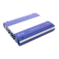
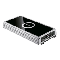
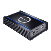
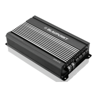
Diagram illustrating the physical installation of the amplifier.
Diagram showing power supply, ground, and remote connections.
Diagram detailing front/rear RCA inputs and control features.
Diagram for stereo or bridged mono speaker connections.
Diagram for stereo or bridged mono speaker connections with 2 Ohm load.
Diagram for stereo or bridged mono speaker connections (2 Ohm load).
Diagram for bridge mode speaker connections with 4 Ohm load.