EasyManua.ls Logo

Blaupunkt MVP 01 - Page 3

Blaupunkt MVP 01
63 pages
Print Icon
To Next Page IconTo Next Page
To Previous Page IconTo Previous Page
Loading...
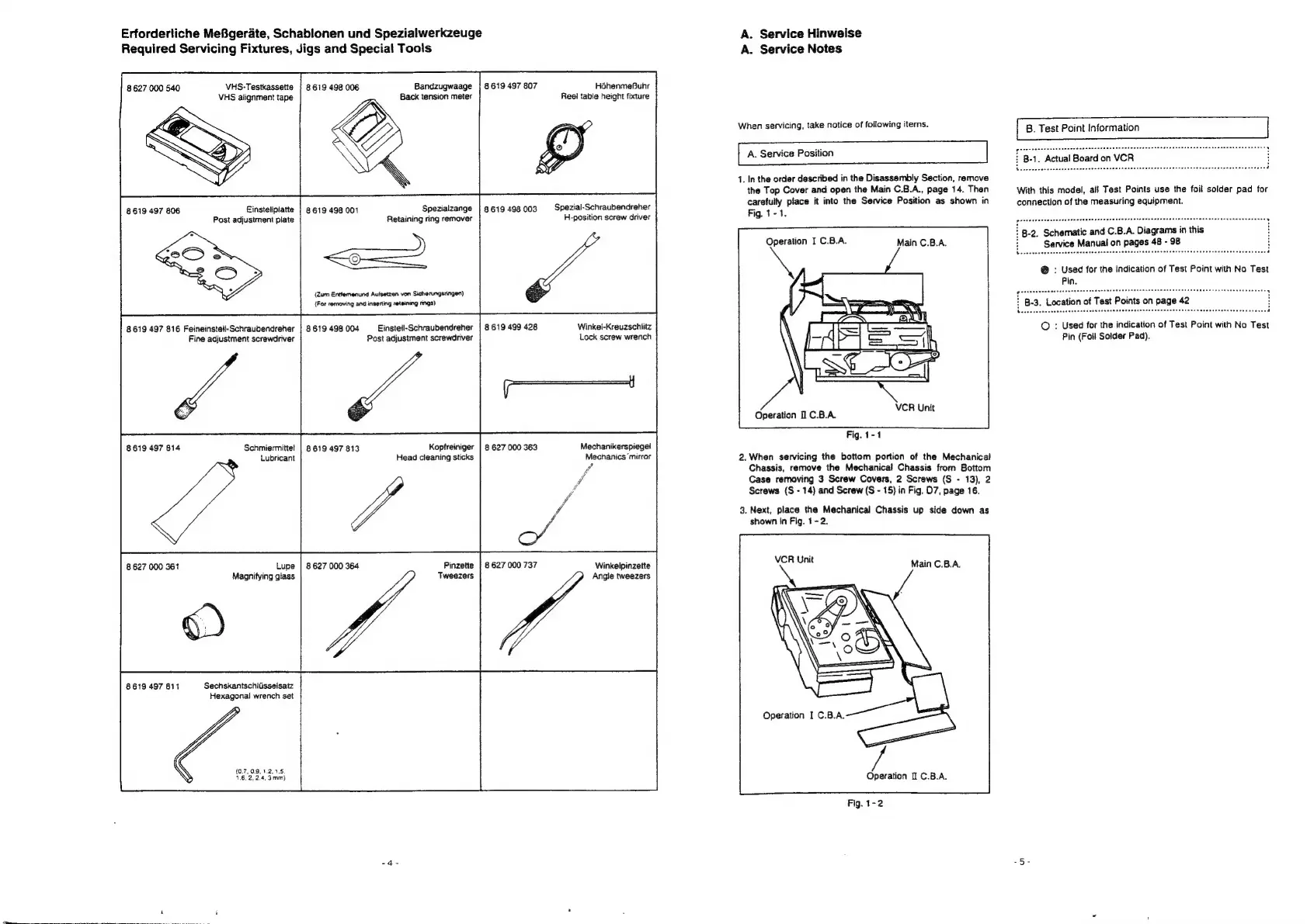
Erfordertiche
MeBgerate,
Schablonen
und
Spezialwerkzeuge
Required
Servicing
Fixtures,
Jigs
and
Special
Tools
VHS-Testkassette
VHS
alignment
tape
8
627
000
540
Einstelpiatte
Post
adjustment
plate
8619
497
806
8619
497
816
Feineinstell-Schraubendreher
Fine
adjustment
screwdriver
8619
497
814
Schmiermittel
Lubricant
8
627
000
361
Lupe
Magnifying
glass
Sechskantschlisseisatz
Hexagonal
wrench
set
8619
497
811
8619
498 006
Bandzugwaage
Back
tension
meter
Spezialzange
Retaining
ring
remover
ea
(Zum
Enttemenund
Aufsetzen
von
Sicherungsringen)
{For
removing
and
inserting
retaining
rings)
8
619 498
001
8619
498
004
Einstell-Schraubendreher
Post
adjustment
screwdriver
of
Kopfreiniger
Head
cleaning
sticks
VA
8
627
000 364
Pinzette
8619
497
813
8619
497
807
8619
498
003
8
619
499
428
8
627
000
363
8
627
000
737
Héhenmefuhr
Ree!
table
height
fixture
Spezial-Schraubendreher
H-position
screw
driver
Winkel-Kreuzschiitz
Lock
screw
wrench
Mechanikerspiege!
Mechanics
‘mirror
Winkelpinzette
Angle
tweezers
A.
Service
Hinweise
A.
Service
Notes
When
servicing,
take
notice
of
following
items.
A.
Service
Position
1.
In
the
order
described
in
the
Disassembly
Section,
remove
the
Top
Cover
and
open
the
Main
C.8.A.,
page
14.
Then
carefully
place
it
into
the
Service
Position
as
shown
in
Fig.
1-1.
Operation
I
C.B.A.
Main
C.B.A.
Operation
1
C.B.A.
VCR
Unit
Fig.
1-1
2.
When
servicing
the
bottom
portion
of
the
Mechanical
Chassis,
remove
the
Mechanical
Chassis
from
Bottom
Case
removing
3
Screw
Covers,
2
Screws
(S
-
13),
2
Screws
(S
-
14)
and
Screw
(S
-
15)
in
Fig.
D7,
page
16.
3.
Next,
place
the
Mechanical
Chassis
up
side
down
as
shown
In
Fig.
1-2.
VCR
Unit
Main
C.B.A.
Operation
I
C.B.A.
Fig.
1-2
B.
Test
Point
Information
B-1.
Actual
Board
on
VCR
With
this
model,
al!
Test
Points
use
the
foil
solder
pad
for
connection
of
the
measuring
equipment.
B-2.
Schematic
and
C.B.A.
Diagrams
in
this
i
Service
Manual
on
pages
48
-
98
©
:
Used
for
the
indication
of
Test
Point
with
No
Test
Pin
(Foll
Solder
Pad).

Related product manuals