EasyManua.ls Logo

Blaupunkt MVP 01 - Page 4

Blaupunkt MVP 01
63 pages
Print Icon
To Next Page IconTo Next Page
To Previous Page IconTo Previous Page
Loading...
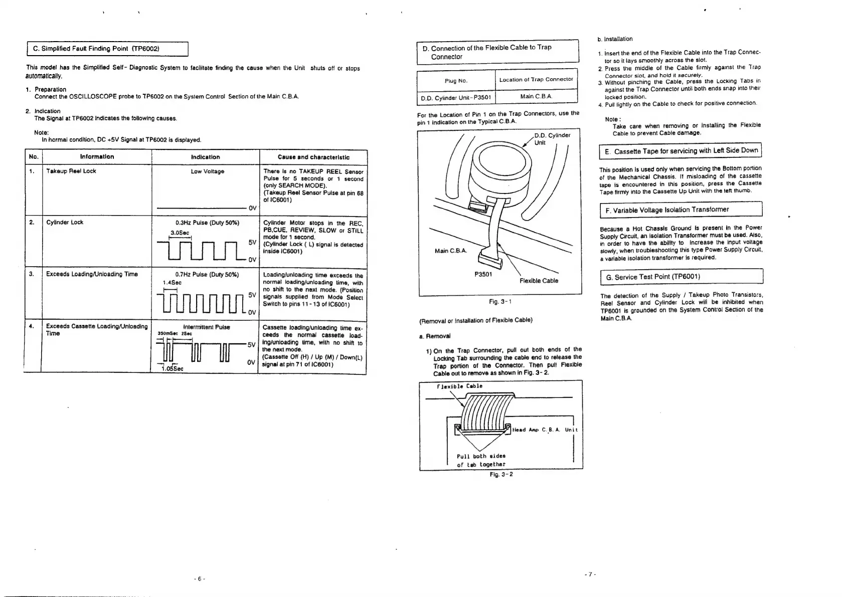
C.
Simplified
Fauit
Finding
Point
(TP6002)
This
model
has
the
Simplified
Self-
Diagnostic
System
to
facilitate
finding
the
cause
when
the
Unit
shuts
off
or
stops
automatically.
1.
Preparation
Connect
the
OSCILLOSCOPE
probe
to
TP6002
on
the
System
Control
Section
of
the
Main
C.B.A.
2.
Indication
The
Signal
at
TP6002
indicates
the
foliowing
causes.
Note:
In
hormal
condition,
DC
+5V
Signal
at
TP6002
is
displayed.
fe]
ween
[i
‘|
1.
|
Takeup
Reel
Lock
Low
Voltage
There
Is
no
TAKEUP
REEL
Sensor
Pulse
for
5
seconds
or
1
second
(only
SEARCH
MODE).
(Takeup
Reel
Sensor
Puise
at
pin
68
ot
1C6001)
Cylinder
Lock
0.3Hz
Pulse
(Duty
50%)
3.0Sec
f———1
Cylinder
Motor
stops
in
the
REC,
PB,CUE,
REVIEW,
SLOW
or
STILL
mode
for
1
second.
{Cylinder
Lock
(
L)
signal
is
detected
inside
1C6001)
Exceeds
Loading/Unloading
Time
0.7Hz
Pulse
(Duty
50%)
1.4Sec
b—
Loading/unloading
time
exceeds
the
normal
loading/unloading
time,
with
no
shift
to
the
next
mode.
(Position
signals
supplied
from
Mode
Select
Switch
to
pins
11-
13
of
1C6001)
Exceeds
Cassette
Loading/Unloading
Time
intermittent
Pulse
Cass
ing
ti
ssbciled-obes
ette
loading/unloading
time
ex-
ceeds
the
normal
cassetie
load-
Sr
5\
|
ing/unloading
time,
with
no
shift
to
the
next
mode.
(Cassette
Off
(H)
/
Up
(M)
/
Down(L)
ee
Plt
OV
|
signal
at
pin
71
of
1C6001)
D.
Connection
of
the
Flexible
Cable
to
Trap
Connector
ee
eee
D.D.
Cylinder
Unit-
P3501
Main
C.B.A.
For
the
Location
of
Pin
1
on
the
Trap
Connectors,
use
the
pin
1
indication
on
the
Typical
C.B.A.
D.O.
Cylinder
Unit
Flexible
Cable
Fig.
3-1
(Removal
or
installation
of
Flexible
Cable)
a.
Removal
4)
On
the
Trap
Connector,
pull
out
both
ends
of
the
Locking
Tab
surrounding
the
cable
end
to
release
the
Trap
portion
of
the
Connector.
Then
pull
Fiexible
Cable
out
to
remove
as
shown
in
Fig.
3-
2.
Flexible
Cable
Head
Amp
C.B.A.
Unit
Pull
beth
sides
of
tab
together
b.
Installation
1.
Insert
the
end
of
the
Flexible
Cable
into
the
Trap
Connec-
tor
so
it
lays
smoothly
across
the
slot.
Press
the
middie
of
the
Cable
firmly
against
the
Trap
Connector
slot,
and
hoid
it
securely.
.
Without
pinching
the
Cable,
press
the
Lacking
Tabs
in
against
the
Trap
Connector
until
both
ends
snap
into
their
locked
position.
_
Pull
lightly
on
the
Cable
to
check
for
positive
connection.
Le)
wo
b
Note:
Take
care
when
removing
or
installing
the
Flexible
Cable
to
prevent
Cable
damage.
E.
Cassette
Tape
for
servicing
with
Left
Side
Down
This
position
Is
used
only
when
servicing
the
Bottom
portion
of
the
Mechanical
Chassis.
If
misloading
of
the
cassette
tape
is
encountered
in
this
position,
press
the
Cassette
Tape
firmly
into
the
Cassette
Up
Unit
with
the
teft
thumb.
F.
Variable
Voltage
Isolation
Transformer
Because
a
Hot
Chassis
Ground
is
present
in
the
Power
Supply
Circuit,
an
Isolation
Transformer
must
be
used.
Also,
in
order
to
have
the
ability
to
Increase
the
input
voltage
slowly,
when
troubleshooting
this
type
Power
Supply
Circuit,
a
variable
isolation
transformer
is
required.
G.
Service
Test
Point
(TP6001)
The
detection
of
the
Supply
/
Takeup
Photo
Transisto:s,
Reel
Sensor
and
Cylinder
Lock
will
be
inhibited
when
TP6001
is
grounded
on
the
System
Control
Section
of
the
Main
C.B.A.

Related product manuals