EasyManua.ls Logo

Blaupunkt MVP 01 - Page 6

Blaupunkt MVP 01
63 pages
Print Icon
To Next Page IconTo Next Page
To Previous Page IconTo Previous Page
Loading...
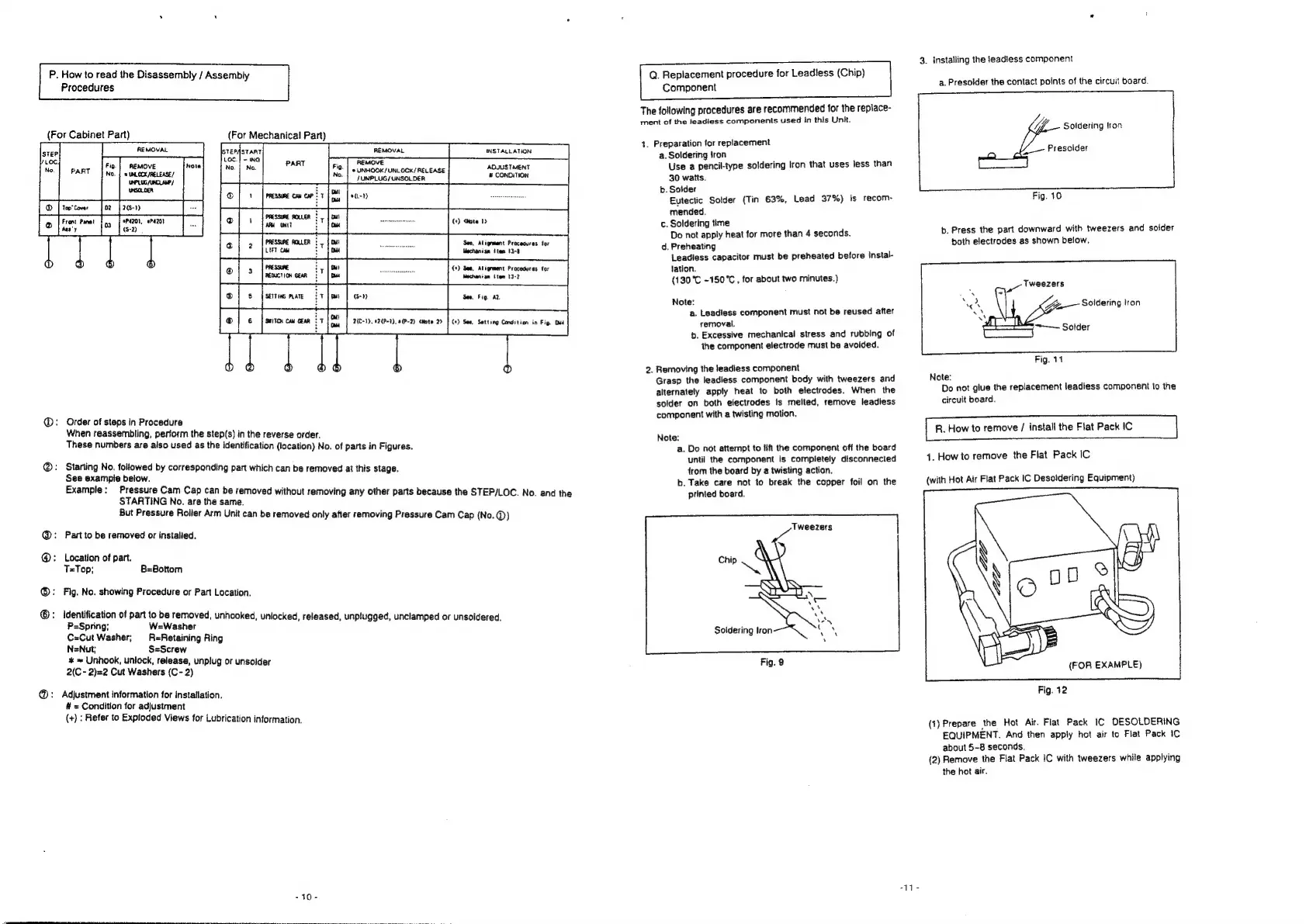
P.
How
to
read
the
Disassembly
/
Assembly
Procedures
(For
Cabinet
Part)
(For
Mechanica!
Part)
ae
a
ae
®
UNHOOK/UNLOCK/
RELEASE
ADJUSTMENT
/UNPLUG/UNSOLDER
-CONENON
ee
Ses,
Alignment
Procedures
for
Mechanisa
iten
13-2
aE
SETTING
PLATE
it
(+)
Sea,
Aligrment
Procedures
tor
Mechanism
(tee
13-2
2(C-1),
24P-1),
4(P-2)
cMote
2>
|
(+)
Sea,
Setting
Condition
in
Fig
Dud
@®:
Order
of
steps
in
Procedure
When
reassembling,
perform
the
step(s)
in
the
reverse
order.
These
numbers
are also
used
as
the
identification
(location)
No.
of
parts
in
Figures.
@®:
Starting
No.
followed
by
corresponding
part
which
can
be
removed
at
this
stage.
See
example
below.
Example:
Pressure
Cam
Cap
can
be
removed
without
removing
any
other
parts
beca
Abseasiivar
thane
nadig
9
any
Pp
use
the
STEP/LOC.
No.
and
the
But
Pressure
Roller
Arm
Unit
can
be
removed
only
after
removing
Pressure
Cam
Cap
(No.@)
@:
Part
to
be
removed
or
installed.
@:
Location
of
part.
T=Top;
B=Bottom
®:
Fig.
No.
showing
Procedure
or
Part
Location.
©:
Identification of
part
to
be
removed,
unhooked,
unlocked,
released,
unplugged
d
'
.
5
,
,
unclamped
o}
P=Spring;
W=Washer
Bee
atic
C=Cut
Washer,
A=Retaining
Ring
N=Nut;
S=Screw
%
=
Unhook,
unlock,
release,
unplug
or
unsolder
2(C-
2)=2
Cut
Washers
(C-
2)
@:
Adjustment
information
for
installation.
#
=
Condition
for
adjustment
(+)
:
Refer
to
Exploded
Views
for
Lubrication
intormation.
Q.
Replacement
procedure
for
Leadiess
(Chip)
Component
The
following
procedures
are
recommended
for
the
replace-
ment
of
the
leadiess
components
used
In
this
Unit.
4.
Preparation
for
replacement
a.
Soldering
tron
Use
a
pencil-type
soldering
Iron
that
uses
less
than
30
watts.
b.
Soider
Eutectic
Solder
(Tin
63%,
Lead
37%)
is
recom-
mended.
c.
Soldering
time
Do
not
apply
heat
for
more
than
4
seconds.
d.
Preheating
Leadless
capacitor
must
be
preheated
before
Instal-
lation.
{130°C
-150°C
,
for
about
two
minutes.)
Note:
a.
Leadless
component
must
not
be
reused
after
removal.
b.
Excessive
mechanical
stress
and
rubbing
of
the
component
electrode
must
be
avoided.
2.
Removing
the
leadiess
component
Grasp
the
leadiess
component
body
with
tweezers
and
alternately
apply
heat
to
both
electrodes.
When
the
solder
on
both
electrodes
is
melted,
remove
leadless
component
with
a
twisting
motion.
Note:
a.
Do
not
attempt
to
lift
the
component
off
the
board
until
the
component
is
completely
disconnected
trom
the
board
by
a
twisting
action.
b.
Take
care
not
to
break
the
copper
foil
on
the
printed
board.
Soldering
Iron
Fig.
9
3.
installing
the
jeadiess
component
a.
Presolder
the
contact
points
of
the
circuit
board.
YA
Soldering
fron
Z_—~
Presoider
eal
ee
Fig.
10
b.
Press
the
part
downward
with
tweezers
and
solder
both
electrodes
as
shown
below.
uv
Wweezers
Glia
Soldering
tron
~——
Solder
Fig.
11
Note:
Do
not
glue
the
replacement
leadiess
component
to
the
circuit
board.
R.
How
to
remove
/
install
the
Flat
Pack
IC
1.
How
to
remove
the
Flat
Pack
IC
(with
Hot
Air
Flat
Pack
IC
Desoldering
Equipment)
(FOR
EXAMPLE)
Fig.
12
(1)
Prepare
the
Hot
Air.
Fiat
Pack
IC
DESOLDERING
EQUIPMENT.
And
then
apply
hot
air
to
Flat
Pack
IC
about
5~8
seconds,
(2)
Remove
the
Flat
Pack
IC
with
tweezers
while
applying
the
hot
air.

Related product manuals