Do you have a question about the Blaupunkt THA 275 PnP and is the answer not in the manual?
Details manufacturer warranty for products purchased within the European Union.
Guidance on ensuring optimal performance through correct installation by trained personnel.
Warning about potential permanent hearing damage from prolonged high sound pressure levels.
Mandatory safety precautions to observe before and during the installation process.
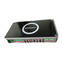
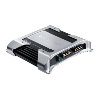
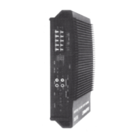
Instructions for securing the amplifier and selecting a suitable installation location.
Guidelines for fitting the amplifier power cable with a fuse near the battery for protection.
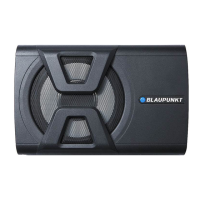
Specifications for connecting loudspeakers, including impedance and maximum power handling.
Highlights the amplifier's suitability for vehicle-specific plug-and-play adapters and ISO connections.
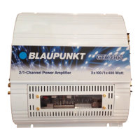
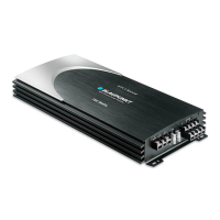
Details on stereo and bridge modes, including power ratings and connection diagrams.
Provides the physical dimensions of the THA 275 PnP amplifier in millimeters and inches.
Instructions for connecting the 12V positive cable, routing it via fuse, and securing the minus cable to an earth point.
Explains the function of integrated fuses in protecting the amplifier and electrical system.
References to figures illustrating various connection types like voltage supply, cinch, loudspeaker, and AUX.
Details on connecting the amplifier for remote switching via the radio's on/off switch or automatically with PnP cables.
Information on connecting to radio devices without pre-stage outputs using high-level (PnP) inputs.
Guide for connecting NF sources like MP3 players or navigation devices via a 3.5-mm jack plug.
Instructions for installing the optional 5-m jack plug cable, including its on/off switch feature.
Guidance on using the Level control to adjust input sensitivity to match the car sound system's output voltage.
Emphasis on correct polarity for amplifier and loudspeaker connections for optimal bass response.
Instructions for bridging channels 1+2 for mono output, suitable for subwoofers or mid-range drivers.
Information on responsible product disposal using available return and collection systems.
How to adjust the type and range of frequency crossovers (High-Pass and Low-Pass) for loudspeakers.
Explanation of the automatic amplifier switch-on when using a PnP INPUT cable, eliminating the need for a remote cable.
Description of the green (power on) and red (error/protection) LEDs indicating the amplifier's status.
Diagram showing the general mounting of the amplifier unit within a vehicle.
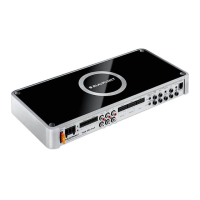
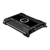
Detailed diagram illustrating the main input and output connections for the amplifier.
Explanation for PnP High-Input connection, specifically for car radios with bridged output stages.
Diagram illustrating the power supply and speaker wiring connections.
Diagram showing the power supply and ground wiring connections, including fuse placement.
Diagram illustrating audio input and output connections using RCA (cinch) connectors.
Diagram for connecting two stereo loudspeakers, specifying minimum impedance.
Diagram for connecting two stereo loudspeakers, detailing impedance requirements for optimal performance.
Diagram showing how to connect an external audio source via the Direct AUX input using a jack plug.
Overall wiring diagram illustrating the connection of the amplifier to the vehicle's power and audio system.
Provides phone and fax numbers for Blaupunkt service centers in various countries.
| Impedance | 2 Ω |
|---|---|
| Frequency range | 10 - 30000 Hz |
| RMS rated power | 180 W |
| Audio output channels | 2.0 channels |
| Signal-to-Noise Ratio (SNR) | 95 dB |
| Total Harmonic Distortion (THD) | 0.05 % |
| Equalizer | Yes |
| Product color | White |
| Audio decoders | Not supported |
| Audio system | No |
| Channels quantity | 2 channels |
| Dimensions (WxDxH) | 159 x 170 x 41 mm |
| Power requirements | 12 V DC |
| Output power description | 4 ohm - 2 x 75 W / 1 x 190 W |
| Connectivity technology | Wired |