blueberry PLUS R2 Installation Manual 3.0 35
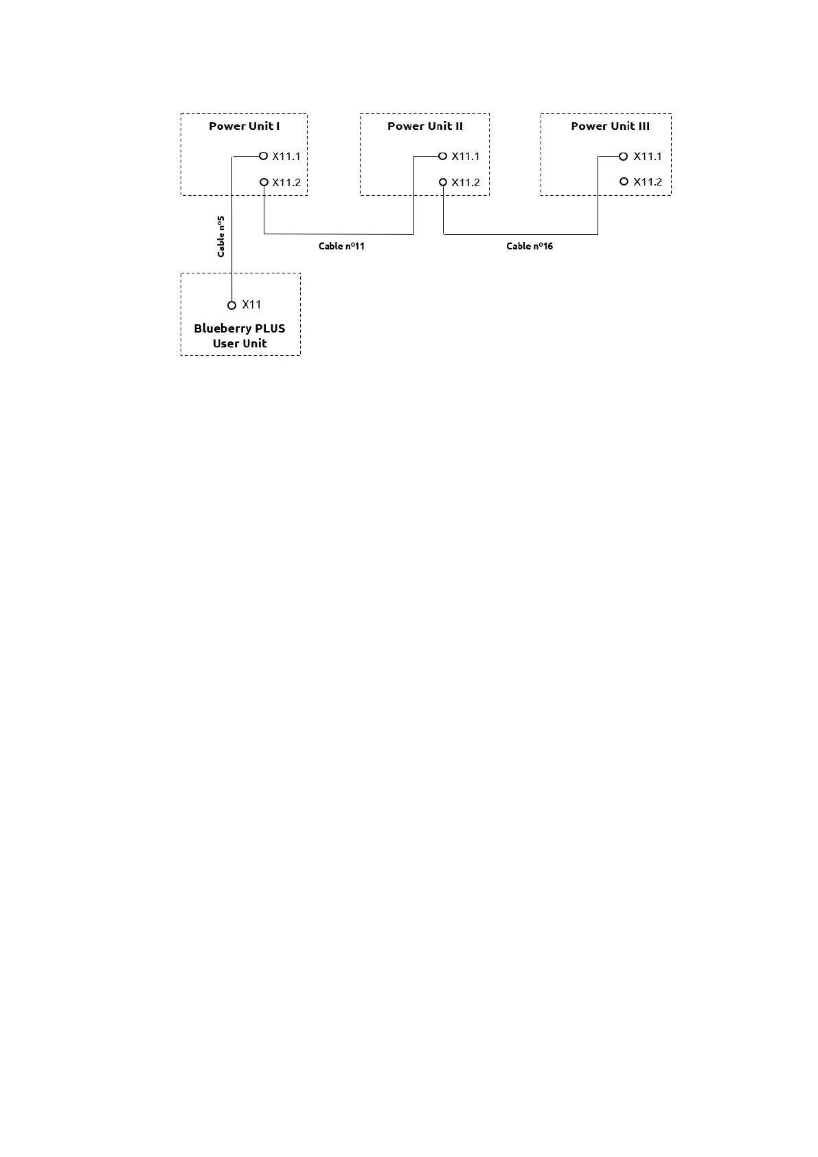
The connection of each ethernet cable depends on the power Unit ID, as shown in the following figure:
Step 9 - Depending on the blueberry PLUS solution, there will be different configurations on the PCB E3
and on terminal block R7 (see image below for components location on the equipment):
• Up to 200kW (one Power Unit)
✓ Nothing to be configured.
• From 250kW to 400kW (two Power Units):
Power Unit I:
✓ PCB E3 - Remove the jumpers P5 and P6
Power Unit II:
✓ PCB E3 - Set the switch SW2 to position “2”
✓ Terminal Block R7 - Remove R7 and apply the new resistor coding (supplied by i-
charging – 160 Ω) marked with “PU II”
• From 450kW to 600kW (three Power Units)
Power Unit I:
✓ PCB E3 - Remove the jumpers P5 and P6
Power Unit II:
✓ PCB E3 - Remove the jumpers P5 and P6 and set the switch SW2 to position “2”
✓ Terminal Block R7 - Remove R7 and apply the new resistor coding (supplied by i-
charging – 160 Ω) marked with “PU II”
Power Unit III:
✓ PCB E3 - Set the switch SW2 to position “3”
✓ Terminal Block R7 - Remove R7 and apply the new resistor coding (supplied by i-
charging – 220 Ω) marked with “PU III”