DANGER!
Make sure that the main switch of the Switchboard power supply that feeds the blueberry
charger product is set to the off position.
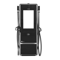
Step 7 - Connect the DC power conductors to the busbars placed in the B side of the Power Unit, as shown in
the image. For that, it is necessary to crimp an M8 ring terminal on the cable and then to tight it with an M8
screw and its matching washer and nut, applying a tightening torque of 28 N.m.
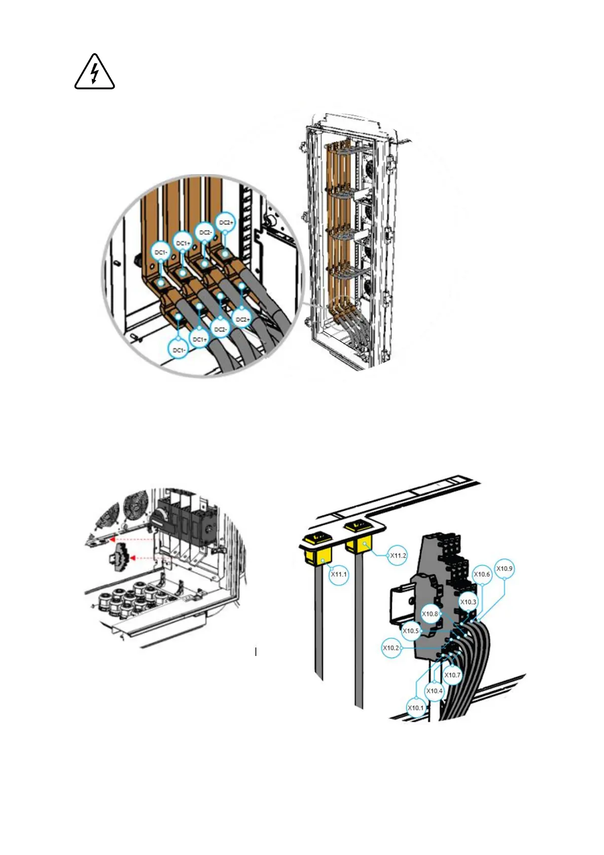
Step 8 - Connect the signal conductors to the X10 terminal block and the ethernet cable (see figure below)
to X11.1 and/or X11.2, placed in the bottom of the Power Unit DC side, as shown in the image. For that, it is
necessary to crimp single end terminals on each line of the shielded cable.