blueberry PLUS R2 Installation Manual 3.0 33
DANGER!
Make sure that the main switch of the Switchboard power supply that feeds the blueberry
charger product is set to the off position.
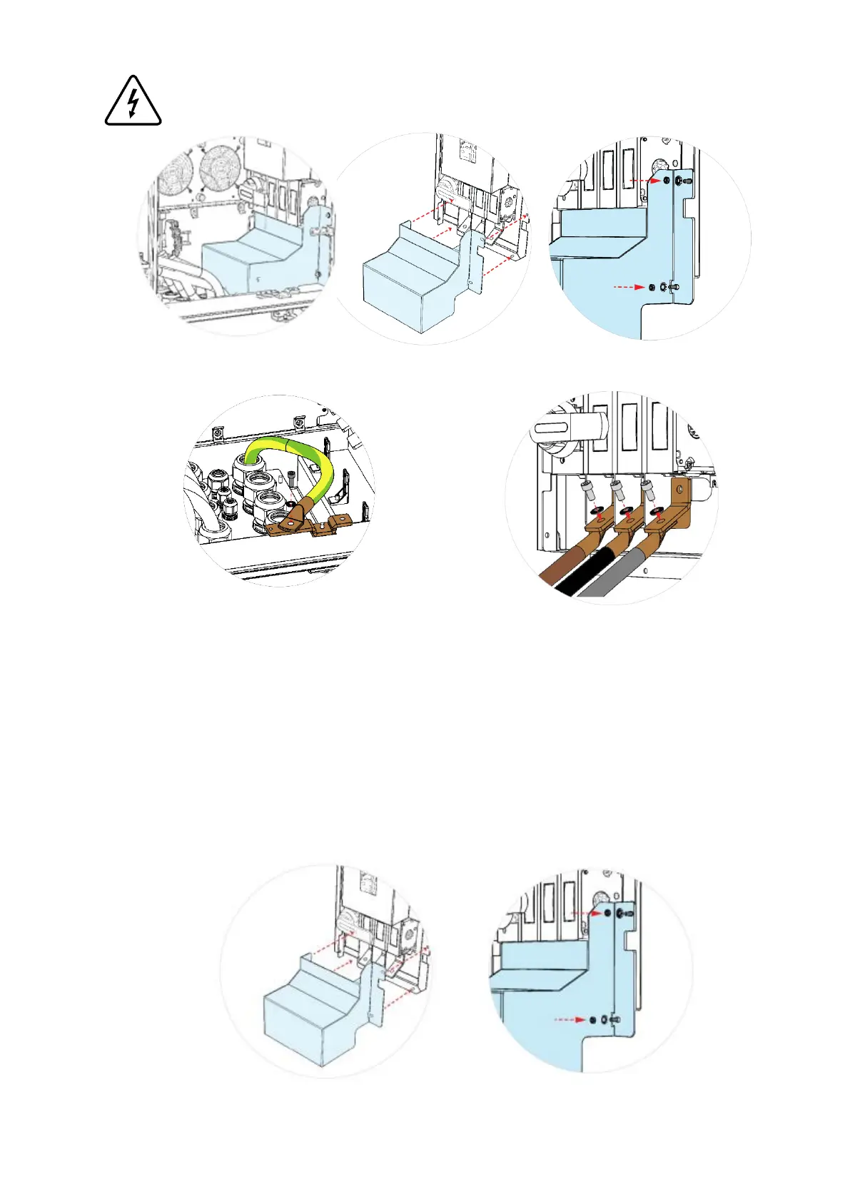
Step 3 – Remove IP2XB protection placed on the bottom of Power Unit (side B) and save the fasteners to
assemble it again in Step 6
Step 4 - Connect the earth cable to the busbar placed
in the bottom of Power Unit (side B). For that, it is
necessary to crimp an M6 ring terminal on the cable
and then to tight the ring terminal with a M6 x 20
screw on the busbar, with a tightening torque of 9
N.m. Please route the cable in a way that it will be
possible to assemble the IP2XB protection again
(Step 6).
Step 5 – Connect the AC power conductors to
the switch disconnector (S1) placed on the
bottom of Power Unit. For that, it is necessary
to crimp a M10 ring terminal on each cable.
Ensure that the phases are connected in a
clockwise direction. Ring terminals shall be
placed below the switch disconnector bars (as
shown in the image above) with an M10 screw
with its matching washer ant nut. Apply a
tightening torque between 30 N.m to 37 N.m.
Step 6 - To ensure IP2XB, the switch disconnector protection shall be assembled again with the same
fasteners.