blueberry PLUS R2 Installation Manual 3.0 32
DANGER!
Make sure that the main switch of the Switchboard power supply that feeds the blueberry
charger product is set to the off position.
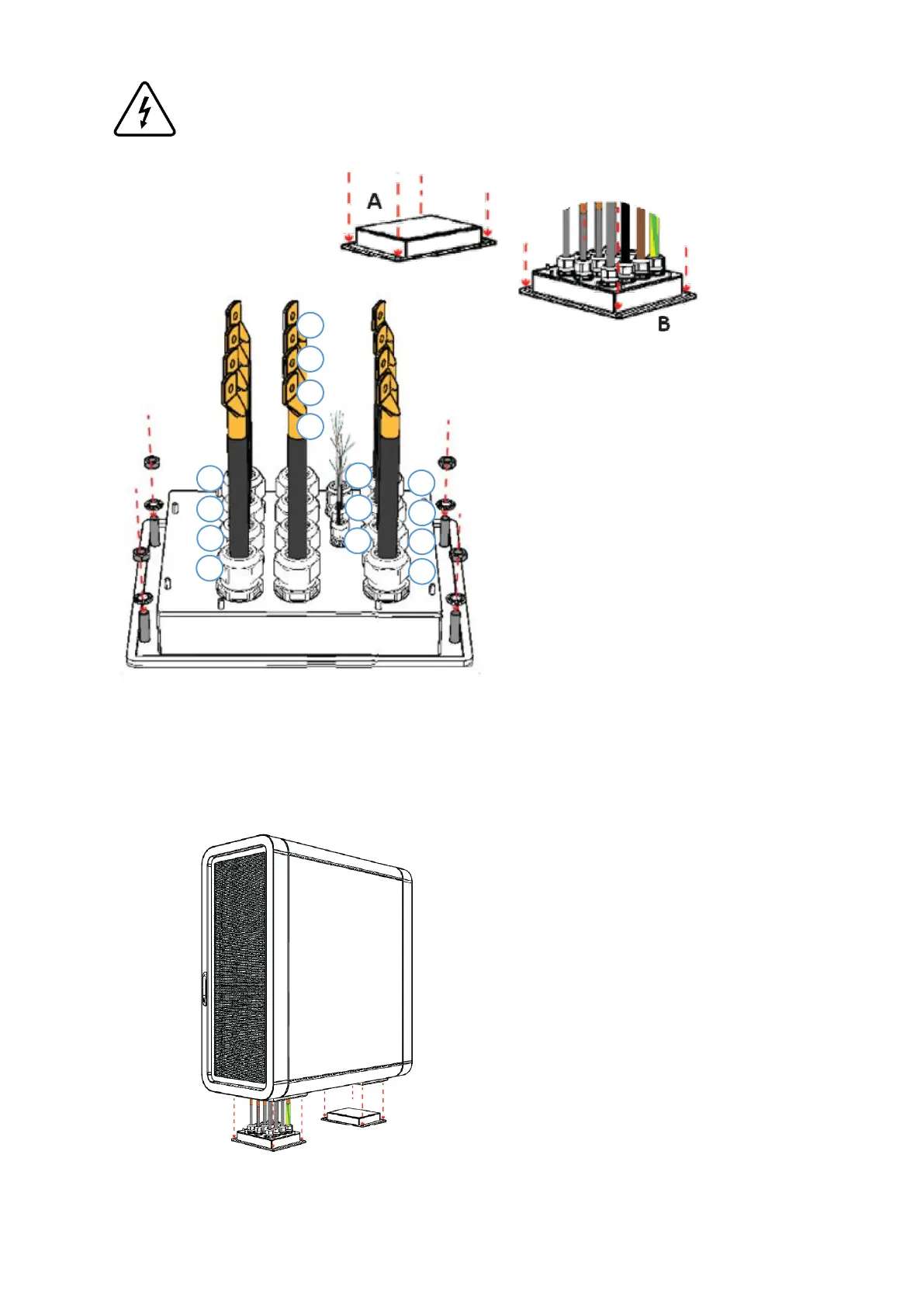
Step 1 – Place the cable gland boxes A and B on the ground floor, matching the holes of each box with the
chemical anchors, and route the AC, DC and communication cables through the cable glands on side B,
according to the image above (Refer to Chapter 5.4 for interconnections).
Step 2 – Place the power unit on the ground floor,
matching the bottom holes with the chemical
anchors and boxes that are already installed.
Make sure that the power unit is placed on the
right position, the side B must be the side of the
box that has cable glands.
Place the matching washers and tight the
hexagonal M12 nuts to fix the two boxes to the
ground, from both sides. Use a ratchet wrench size
18.
The cables ID of α, β and γ depends
on the Power Unit:
Power Unit I
α – Cable nº6
β – Cable nº5
γ – Cable nº11 (If applicable)
Power Unit II
α – Cable nº12
β – Cable nº11
γ – Cable nº16 (If applicable)
Power Unit III
α – Cable nº17
β – Cable nº16