17 BA-100/1EN M52.XXXX
4.1 - Drilling hole groups
4 - Assembly
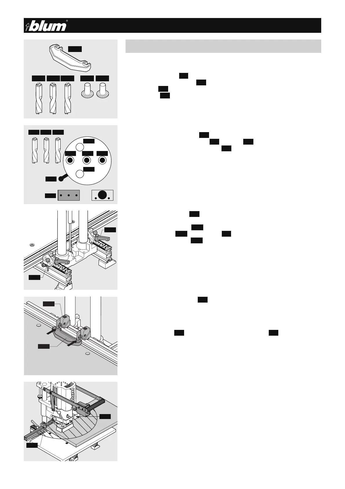
4.1.1) Required parts
• Drill bits:
1x ø 5 mm clockwise (4.1) (marked in black)
2x ø 5 mm counterclockwise (4.2) (marked in red)
• Cover caps (2.3)
• Setup gauge(4.3)
• Carcase side
4.1.2) Setting drill bit length
(See point 2.1.2)
4.1.3) Setting drilling pattern
• Pull sprung loaded knob out (2.5) .
• At the same time, move the lever
(2.6) to symbol (3.3)
• Release knob back to original position
(2.5) .
4.1.4) Inserting drill bits into the chuck
(See point 2.1.4)
4.1.5) Checking drilling depth setting
(see points 2.1.5 / 2.1.6)
4.1.6) Setting stop system (1.4)
• Loosen the clamping lever (2.15) .
• Remove locking pin(2.16) and set gauge (1.4) to SY.
• Secure the clamping lever (2.15) .
This fixed setting provides a drilling distance of 37 mm.
4.1.7) Setting the swivel stops(1.7)
(See point 2.1.8)
4.1.8) Drilling hole groups
• Place setup gauge (4.3) on the stop that has already been set (1.7) and set an additi-
onal stop.
This results in a 6 hole group with a 32 mm hole spacing.
4.1.9) Placing carcase side on the work table and pushing up against the stop
(See point 2.1.9)
4.1.10) Drilling
(See point 2.1.12)
6.3
2.7
L
 Loading...