Do you have a question about the BLUM MINIPRESS P and is the answer not in the manual?
Explains how to navigate and interpret the operating instructions and safety symbols.
Details remaining risks according to ISO EN 12100-2, including stroke movement and safety device failures.
Explains the meaning of various safety decals and symbols used throughout the manual.
Specifies the designated purpose of the assembly machine and prohibited uses.
Presents noise emission levels according to EN ISO 11202 (11204) and discusses workplace values.
Details dust emission control requirements, including connection to a dust extraction system.
Declaration of the product's compliance with EU Directives and harmonised European standards.
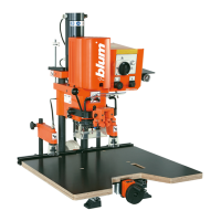
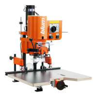
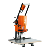
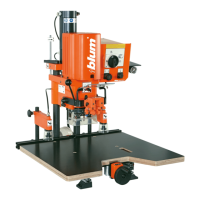
Lists essential technical data including weight, dimensions, power, and installation requirements.
Instructions for unpacking the machine and attaching it to a suitable table.
Details on lifting and securing the assembly machine onto a workbench.
Instructions for attaching the base ruler component (MZE.130M00).
Steps for connecting the compressed air supply to the air filter unit.
Specifies the recommended operating pressure and air consumption per cycle.
Instructions for making the electrical connection, emphasizing qualified electrician.
Steps for connecting the dust extraction system's hose to the machine.
Guidance on electrically connecting the extraction system controller.
Details the main switch, feed switch, hold down clamp switch, and mode display switch.
Explains the function of the feed switch for drilling and insertion processes.
Details how to operate the hold down clamp switch and its modes.
Step-by-step guide for assembling furniture hinges using the machine.
Lists the necessary drill bits, cover caps, insertion ram, and furniture hinge.
Instructions on how to set the correct drill bit length for precise drilling.
Procedure for adjusting the cam speed using the knurled head screw.
Instructions for setting the cam brake stiffness based on wood type.
How to set the desired dimension or fixed setting for the stop system.
Procedure for setting swivel stops to the desired dimension and clamping.
How to place the workpiece and push it against the stop or marking line.
Instructions for adjusting hold down clamps to the material thickness.
How to clip the furniture hinge onto the insertion ram before drilling.
Detailed steps for carrying out the drilling process, including safety precautions.
Instructions for inserting the furniture hinge after drilling.
Lists drill bits, cover caps, cabinet side, and mounting plate with screws.
Instructions to set drill bit length, referencing previous section.
Procedure for setting the drilling pattern for the mounting plate.
Instructions for setting hold down clamps to material thickness.
Steps for performing the drilling operation for the mounting plate.
How to release the hold down clamps after drilling.
Lists drill bits, cover caps, and setup gauge.
Instructions to set drill bit length, referencing previous section.
Steps for drilling hole groups using a setup gauge.
General maintenance procedures for the assembly machine.
Procedure for identifying and replacing a damaged coupling.
Steps for replacing the operational status indicator lamp.
Lists common drilling errors, their causes, and solutions.
Procedure to adjust the laser line to the zero position for accurate alignment.
Steps for adjusting the laser angle for correct alignment on the workpiece.
Procedure to ensure the laser beam is perpendicular to the work surface.
Lists errors related to fitting insertion, their causes, and solutions.
Lists general function errors, their causes, and solutions.
Addresses causes and solutions for motor overheating issues.
Diagnoses issues where stroke movement is absent or incomplete.
Covers issues where hold down clamps are not functioning correctly.
Provides dimensions and material recommendations for user-made work tops.
Schematic showing the electrical connections for a single-phase 230V supply.
Schematic showing the electrical connections for a three-phase 230V supply.
Schematic showing the electrical connections for a three-phase 400V supply.
Schematic illustrating the pneumatic system and its components.
| Brand | BLUM |
|---|---|
| Model | MINIPRESS P |
| Category | Power Tool |
| Language | English |