2.1 - Description of operator panels
2 - Description of operator panels
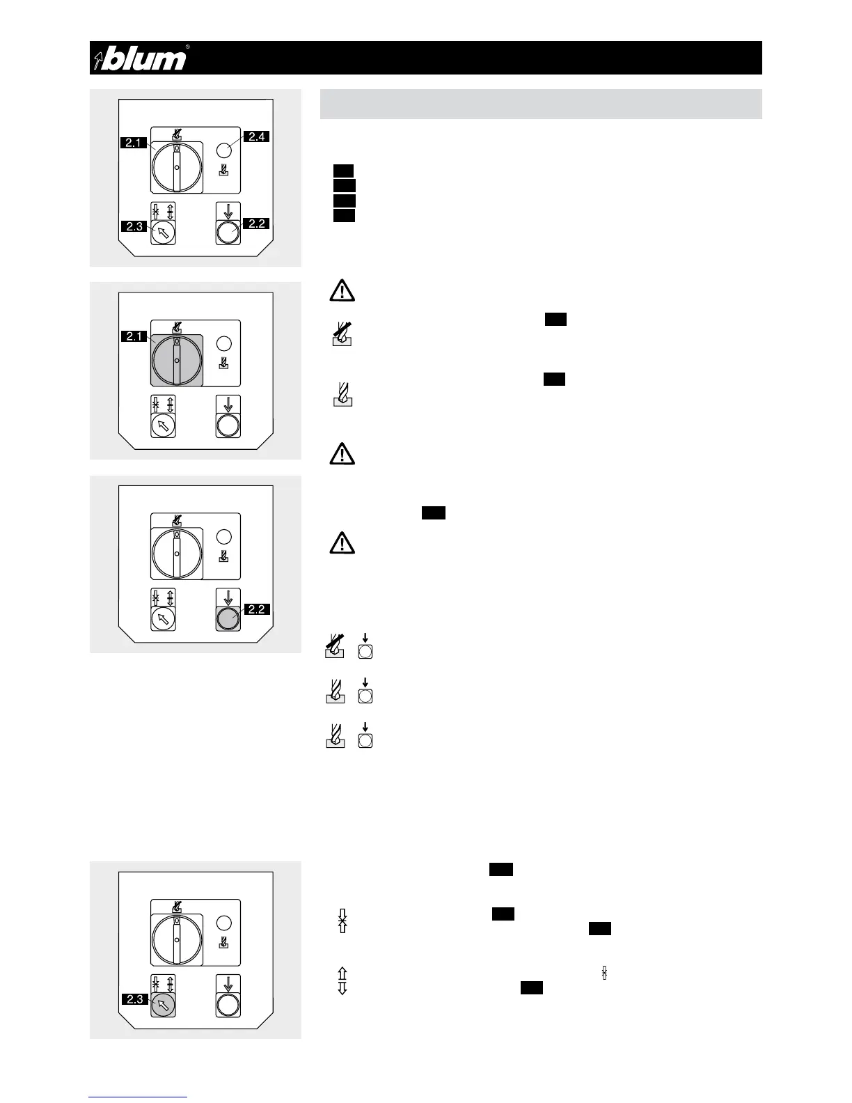
2.1.1) Designation of operating elements
• (2.1) Main switch
• (2.2) Feed switch
• (2.3) Hold down clamp switch
• (2.4) Operating mode display switch
ATTENTION:
The main switch does not disconnect the assembly machine
from the air pressure system.
Pos.0: Operational status indicator (2.4) does not light. Assembly machine in
set-up mode
- Motor cannot be started
- Stroke movement can be carried out
Pos.1: Operational status indicator (2.4) lights. Assembly machine is in opera-
tional mode
- Drilling and the fitting insertion can be carried out
- The marking line lights
Main switch can be secured against unauthorized drilling using a standard padlock.
2.1.2) Feed switch (2.2)
ATTENTION:
When pressing the feed switch, keep your hands away from the work
area (A) of the assembly machine.
Pressing the feed switch will carry out the currently selected
workprocess.
Set up:
Main switch at Pos.0 + feed switch pressed
Drill:
Main switch at Pos.1 + feed switch pressed
Insert fitting:
Swivel in swing arm + press feed switch
2.1.3) Hold down clamp switch (2.2)
Option: Hold down clamps are not standard equipment.
Pos. Clamps on:
Pressing the feed switch (2.2) automatically engages the hold down clamps.
Briefly touching the hold down clamp switch (2.3) will disengage the clamps.
Pos. Clamps off:
Pressing and turning the clamp switch to Pos.
will turn off the hold down
clamps. When the feed switch (2.2) is pressed, the hold down clamps remain
engaged.
ATTENTION:
For long durability of the laser the main switch should be set on
pos. 0 when not operating.
+
+
+
 Loading...