5.1 - Drilling hole groups
5 - Assembly
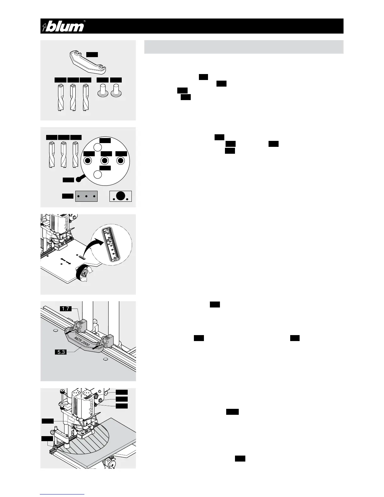
5.1.1) Required parts
• Drill bits:
1x ø 5 mm clockwise (5.1) (marked in black)
2x ø 5 mm counterclockwise (5.2) (marked in red)
• Cover caps (3.3)
• Setup gauge (5.3)
• Cabinet Side
5.1.2) Setting drill bit length
(See point 3.1.2)
5.1.3) Setting drilling pattern
• Pull drilling head fixing knob (3.5).
• At the same time, move the lever (3.6) to the symbol (4.3)
• Release drilling head fixing knob (3.5).
5.1.4) Inserting drill bits into the chuck
(See point 3.1.4)
5.1.5) Checking drilling depth setting
(See point 3.1.5 / 3.1.6)
5.1.6) Setting cam speed
(See point 3.1.5 / 3.1.8 / 3.1.9)
5.1.7) Setting stop system
• Set the desired dimension using the hand wheel
• or set the stop system to SY using this fixed setting (the drilling distance is 37 mm)
5.1.8) Setting swivel stops (1.7)
(See point 3.1.11)
5.1.9) Drilling hole groups
• Place setup gauge (5.3) on the stop that has already been set (1.7) and set an ad-
ditional stop.
This results in a 7 hole group with a 32 mm hole spacing.
5.1.10) Placing cabinet side on the work top and pushing up against the stop
or marking line
(See point 3.1.12)
5.1.11) Setting hold down clamps (3.17) to the material thickness
(See point 3.1.13)
5.1.12) Drilling
(See point 3.1.16)
5.1.13) Releasing hold down clamps
• Briefly press hold down clamp switch (2.3)
• Push cabinet side to the next stop.
5.3
5.2 5.1 5.2 3.3 3.3
Ø 5 Ø 5 Ø 5
5.2
3.6
4.3
3.3
3.3
5.2 5.1 5.2
5.1 5.2
L
3.8
1.7
 Loading...