P-12
Self-tapping screws (J) - Push the handle flat against the door and ensure that it is vertical, then
fix to the door without overtightening.
Pick up the internal handle (B) and the setting needle (K). At the back of the handle grip, there is a
small hole. Push the setting tool into this hole and press hard until the magnetic handle cover (B-1)
pops off. Remove the cover and also the battery cassette (B-2).
Holding the internal handle (B), feed the wire and spindle through the spindle hole in the handle.
You will be able to see the cable coming through from the back of the handle.
Fix the internal handle to the door:
Through Fixings (H,I) - Use the screws provided (I) and fix the internal handle to the external handle
through the drilled holes. If you can't locate the screws into the pillars on the external handle, it may
be that the holes aren't fully aligned. Repeat step 6 to fix this.
Self-tapping screws (J) Push the handle flat against the door, then fix to the door without
overtightening.
Test the handle. Push the internal handle down, it should operate the latch fully. Then touch the
fingerprint sensor on the external handle, it should light up GREEN and you should hear the
mechanism turn. Push the handle down and it should operate the latch.
Ensuring everything is working correctly, it is now okay to close the door. It is recommended to test
this from the inside, therefore you can still remove the handle if anything isn't working correctly.
Insert 4 AAA batteries into the battery
cassette.
When both handles are fixed, connect
the battery cassette (B-2) to the wire
(you will hear a beep). Then insert the
battery cassette into the handle, ensuring
that the side containing the cable
connector and setting button goes in
first.
Put the magnetic handle cover (B-1)
back onto the handle.
a
b
12
13
14
15
16
17
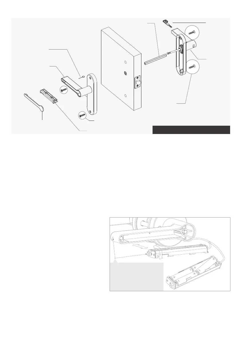
K Setting needle
B-1 Internal handle
cover
B-2 Battery cassette
B-Internal handle
J-Self tapping screw
A-External
handle
J-Self tapping
screw
F Key
G Hollow spindle
Installation Using Self Tapping Screws
Model C Installation
Note: please make sure the
setting button's orientation
is facing the inside of the
handle and aligns with the
hole.
10
11
b
 Loading...