ACM200 API DEVELOPMENT
03
contact support@blustream.co.uk / support@blustream.com.au
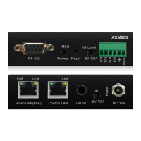
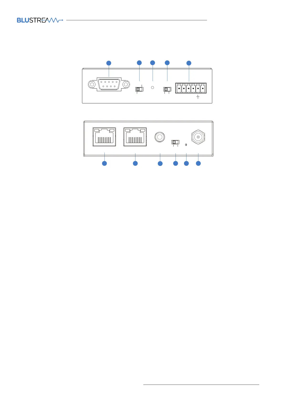
ACM200 - Front Panel
2
1
4
9
8
7
6
1 RS-232 control port – Connect to a
third party control device for control
of the Multicast system using RS-232.
2 MCU Upgrade toggle - for use when
upgrading MCU firmware only.
3 Reset
4 Reserved for future use.
5 GPIO - Reserved for future use.
6 Video LAN (PoE) - Connect to the
layer 3 network switch that the
Blustream Multicast components are
connected to.
7 Control LAN port - Connect to
existing network that your third
party control system resides on. The
Control LAN port is used for Telnet/
IP control of the Multicast system.
Not PoE.
8 IR Ctrl(IR input) – 3.5mm stereo
jack. Connect to third party control
system if you are using IR as your
method of controlling the Multicast
system. When using the Blustream
IRCAB cable (optional) ensure cable
direction is correct.
9 IR - adjust IR voltage level between
5V or 12V input for IR Ctrl.
q Power LED indicator
w Power port – Use 12V 1A DC adaptor
(sold separately) if not using a PoE
network switch.
ACM200 - Rear Panel
Panel Descriptions - ACM200
Video LAN(PoE)
Control LAN
IR Ctrl
IR
5V
12V
DC 12V
Power
Link Link
PoE
IO Level
Reset
VOut
IO4
IO3
IO2
IO1
5V Normal
RS-232
MCU
12V
ACM200
Yellow Green Yellow Green
5
Video LAN(PoE)
Control LAN
IR Ctrl
IR
5V
12V
DC 12V
Power
Link Link
PoE
IO Level
Reset
VOut
IO4
IO3
IO2
IO1
5V Normal
RS-232
MCU
12V
ACM200
Yellow Green Yellow Green
11
3
10
 Loading...