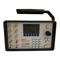
Model 577 Operating Manual 29
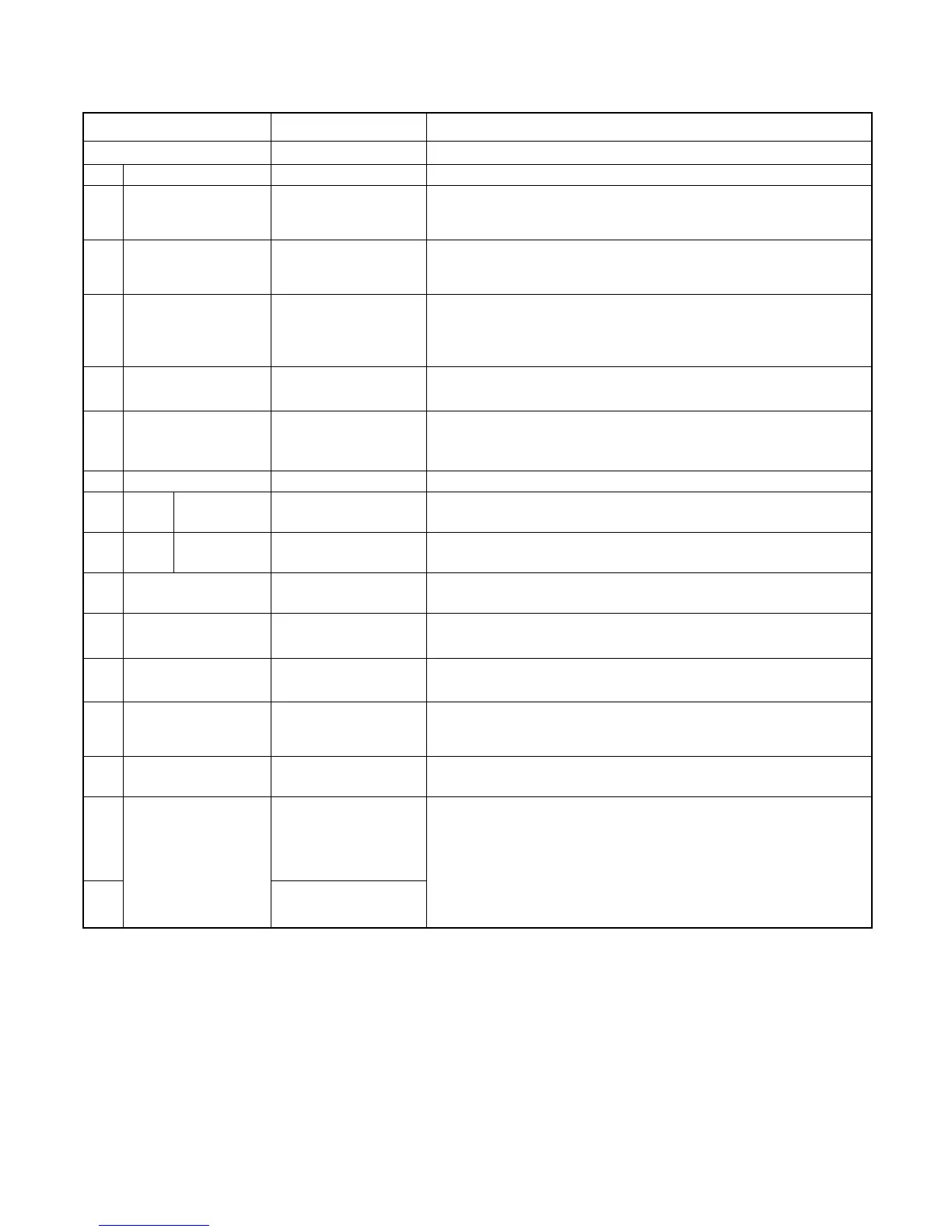
Command to change the units channel specific settings.
enables/disables output pulse for selected channel.
10 ns to
999.999,999,999,75
s
Sets the pulse width for the selected channel.
0 to
999.999,999,999,75
s
Sets the delay from the timing reference to when the pulse is
created.
Allows the user to select the timing reference for each
channel.
*Note: When in external clock input mode T
0
will be the clock
input.
Decimal representation of an 8 bit binary number (example:
255 = 1111 1111)
NORMal,
COMPlement,
INVerted
Normal is active HIGH, Inverted and Complement are active
LOW.
Allows the user to select either TTL logic mode or Adjustable
voltage output mode.
Allows the user to select the voltage potential for Adjustable
output mode.
NORMal, SINGle,
BURSt, DCYCle
Allows the user to select the pattern of outputs to use on the
channel level.
When the channel is in Burst mode will allow user to select
the number of pulses to output with each input clock pulse.
When the channel is in duty cycle mode will allow the user to
select the number of pulses to create with each clock pulse.
When the channel is in duty cycle mode will allow the user to
select the number of pulses to suppress with each clock
pulse.
Allows the user to select how many clock cycles to wait until
the channel should start creating a output pulse.
Allows the user to query the trigger source for that channel
when the gate is used in trigger mode.
*Note: For the gate to be used as a trigger source the unit
must have the dual trigger option.
Sets the channel gate mode to Disabled, Active High or Active
Low mode.