HYDROSTATIC PUMP (Cont'd)
Removal (Cont'd)
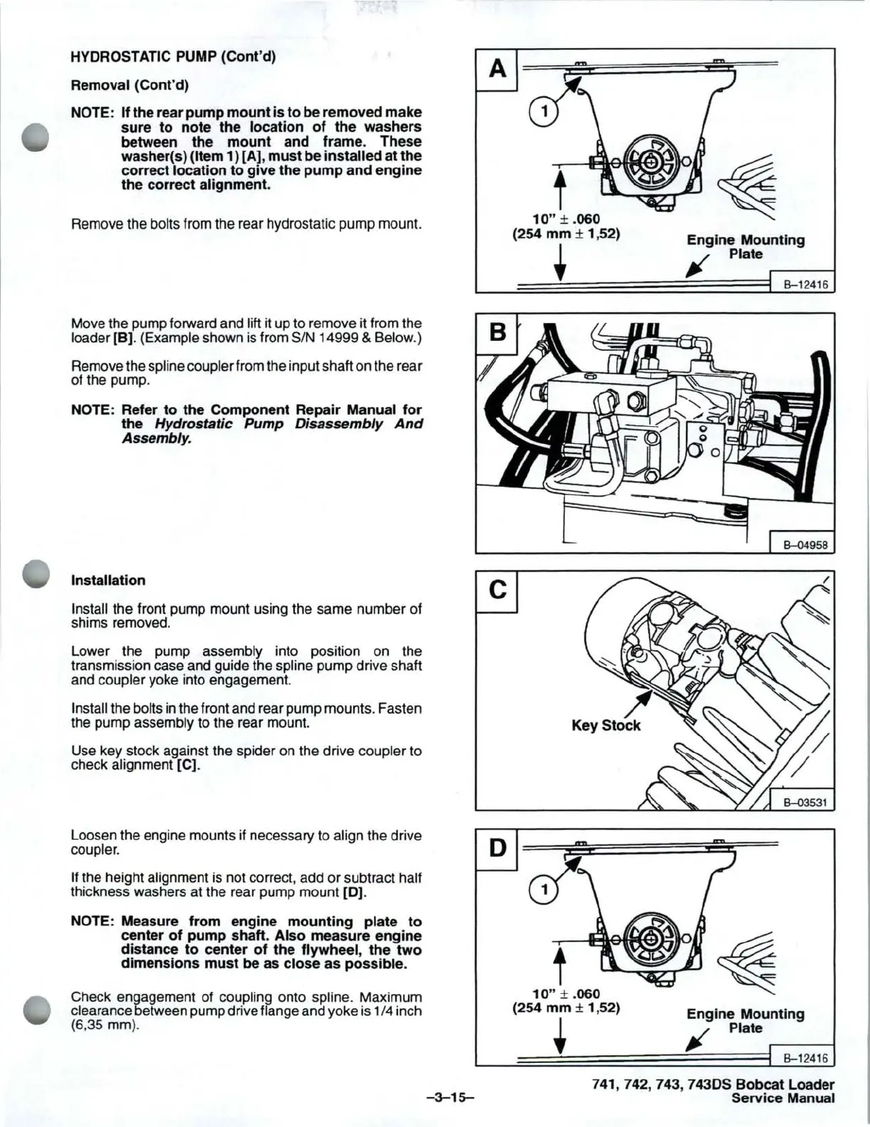
NOTE: If the rear pump
mount
is
to
be removed make
sure
to
note the location
of
the washers
between the
mount
and frame. These
washer(s)
(Item 1) [A],
must
be installed at the
correct
location
to
give the
pump
and engine
the correct
alignment.
Remove the bolts from the rear hydrostatic pump mount.
Move the pump forward and
lift it up to remove it from the
loader
[B].
(Example shown
is
from
SIN
14999 & Below.)
Remove the spline coupler from the input shaft on the rear
of the pump.
NOTE: Refer
to
the Component Repair Manual
for
the Hydrostatic Pump Disassembly
And
Assembly.
Installation
Install the front pump mount using the same number of
shims removed.
Lower the pump
assembly into position on the
transmission case and guide the
spline pump drive shaft
and
coupler yoke into engagement.
Install the bolts in the front and rear pump mounts. Fasten
the pump assembly to the rear mount.
Use key stock against the spider on the drive
coupler to
check alignment
[C].
Loosen the engine mounts if necessary to align the drive
coupler.
If
the height alignment is not correct, add
or
subtract half
thickness washers at the rear pump mount
[0]
.
NOTE: Measure from engine
mounting
plate
to
center
of
pump shaft. Also measure engine
distance
to
center
of
the flywheel, the
two
dimensions
must
be as close as possible.
Check engagement of coupling onto spline. Maximum
clearance between pump drive flange and yoke is
114
inch
(6,35 mm).
A
c
D
-3-15-
"."
t
10"
±
.060
(254
mm
± 1 ,52)
t
"."
t
10"
± .060
(254
mm
± 1,52)
+
"."
Engine Mounting
Jf
Plate
....-----1
B-12416
8-04958
"."
Engine Mounting
Jf
Plate .---
__
-1
B-12416
741, 742, 743,
74305
Bobcat Loader
Service
Manual


 To Next Page
 Loading...