S250 Bobcat Loader
OI-23 Operation & Maintenance Manual
HYDRAULIC CONTROLS (CONT’D)
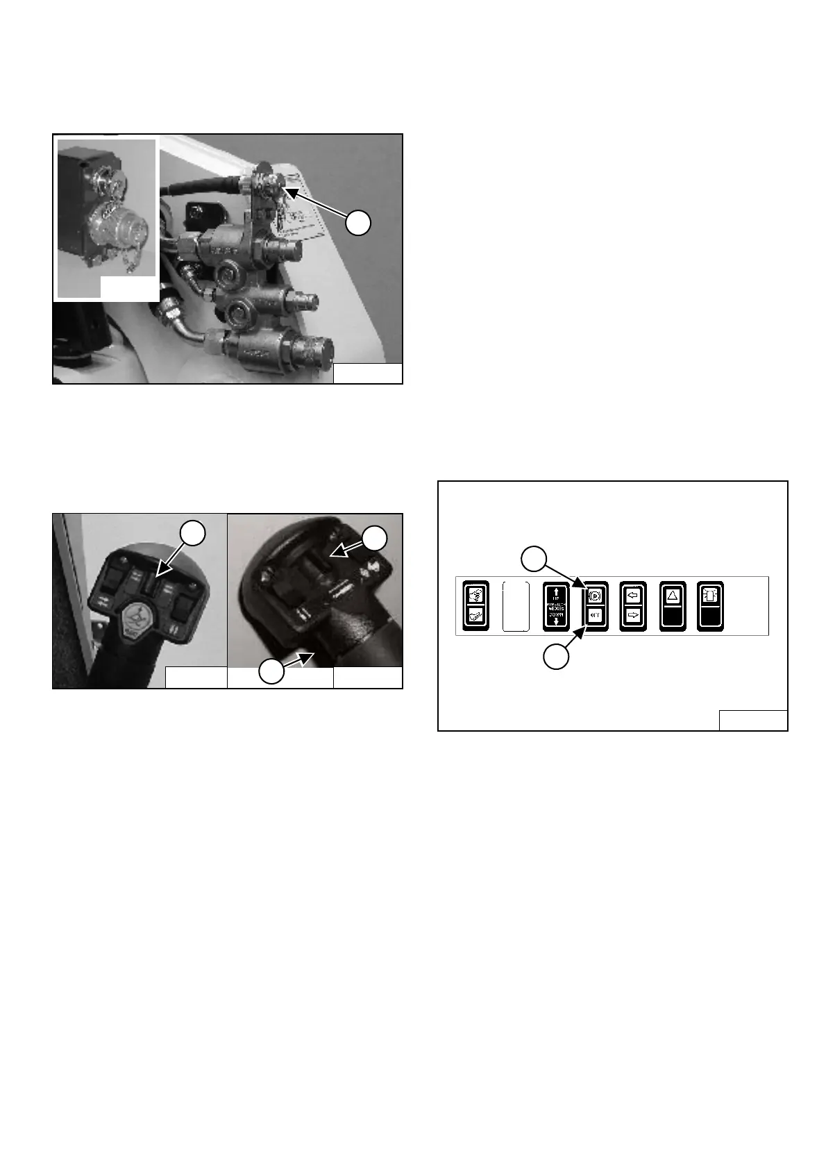
Attachment Control Device (ACD) (If Equipped)
Figure OI-39
You will need the Dual-Connector (7-pin / 14-pin) kit
(Inset) [Figure OI-39] to operate early model
attachments. The 7 pin connector is shown (Item 1)
[Figure OI-39]. See your Bobcat loader dealer.
Figure OI-40
You can use additional switches (Items 1, 2, and 3)
[Figure OI-40] on the right and left control handles for
functions which control some attachments.
See the appropriate Attachment Operation &
Maintenance Manual for control details.
Bucket Position Valve Operation (If Equipped)
The function of the bucket position valve is to keep the
bucket in the same approximate position it is in before
you begin raising the lift arms.
Press BUCKET POSITIONING button (Item 2)
[Figure OI-38] to engage the bucket position function.
(The light will be on.) Press again to disengage.
Bucket Positioning functions only during upward lift cycle.
SHUTDOWN FEATURE
Press and hold the BUCKET POSITIONING button
(Item 2) [Figure OI-38] for 2 seconds. Shtdn will appear
in the HOURMETER / CODE DISPLAY (Item 3)
[Figure OI-38]. (Operational Code will also appear.)
PARKING BRAKE
Operation
Figure OI-41
Press the top of the switch (Item 1) [Figure OI-41] to
engage the parking brake. The traction drive system will
be locked.
Press the bottom of the switch (Item 2) [Figure OI-41] to
disengage the parking brake. The traction drive system
will be unlocked.
NOTE: The TRACTION light on the left instrument
panel will remain OFF until the engine is
started, the PRESS TO OPERATE LOADER
button is pressed and the parking brake is
disengaged.
P-31245
1
P-19820
P-31833
2
1
3
P-16537
B-15993
1
2
 Loading...