107 S650 Operation & Maintenance Manual
ATTACHMENTS (CONT’D)
Installing And Removing The Attachment (Power
Bob-Tach) (Cont’d)
Installing (Cont’d)
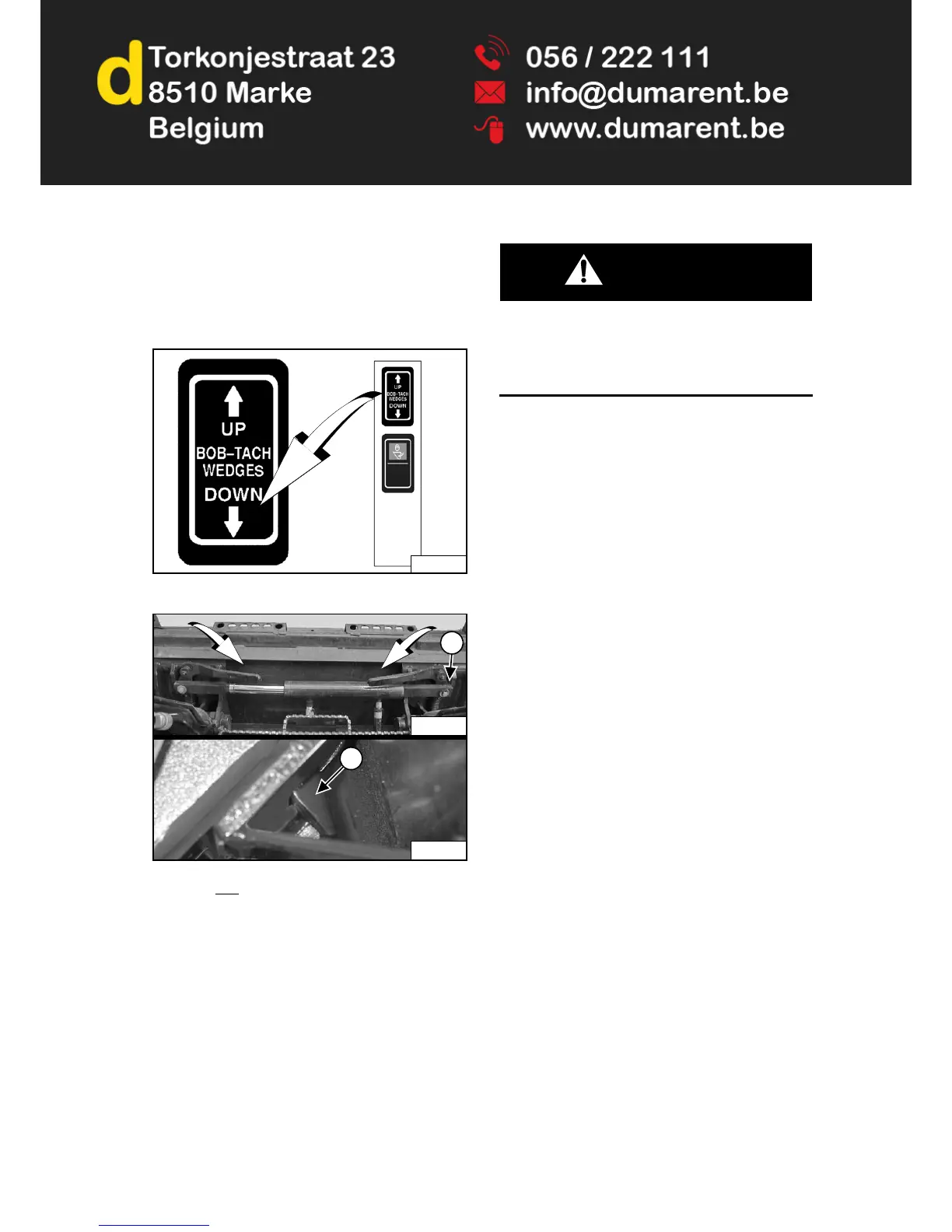
Figure 141
Figure 142
Push and hold
BOB-TACH “WEDGES DOWN” switch
(Right Switch Panel) [Figure 141] until levers are fully
engaged in the locked position [Figure 142] (wedges
fully extended through the attachment mounting frame
holes).
Both levers must contact the frame as shown when
locked (Item 1) [Figure 142].
If both levers do not engage in the locked position, see
your Bobcat dealer for maintenance.
The wedges (Item 2) [Figure 142] must extend through
the holes in the mounting frame of the bucket (or other
attachment), securely fastening the bucket to the Bob-
Tac h.
WARNING
AVOID INJURY OR DEATH
The Bob-Tach wedges must extend through the holes
in the attachment mounting frame. Levers must be
fully down and locked. Failure to secure wedges can
allow attachment to come off.
W-2715-0208
P-85320C
P-85360B
1
P-31233B
2