9
Be careful to assemble all components
in the sequence they are presented.
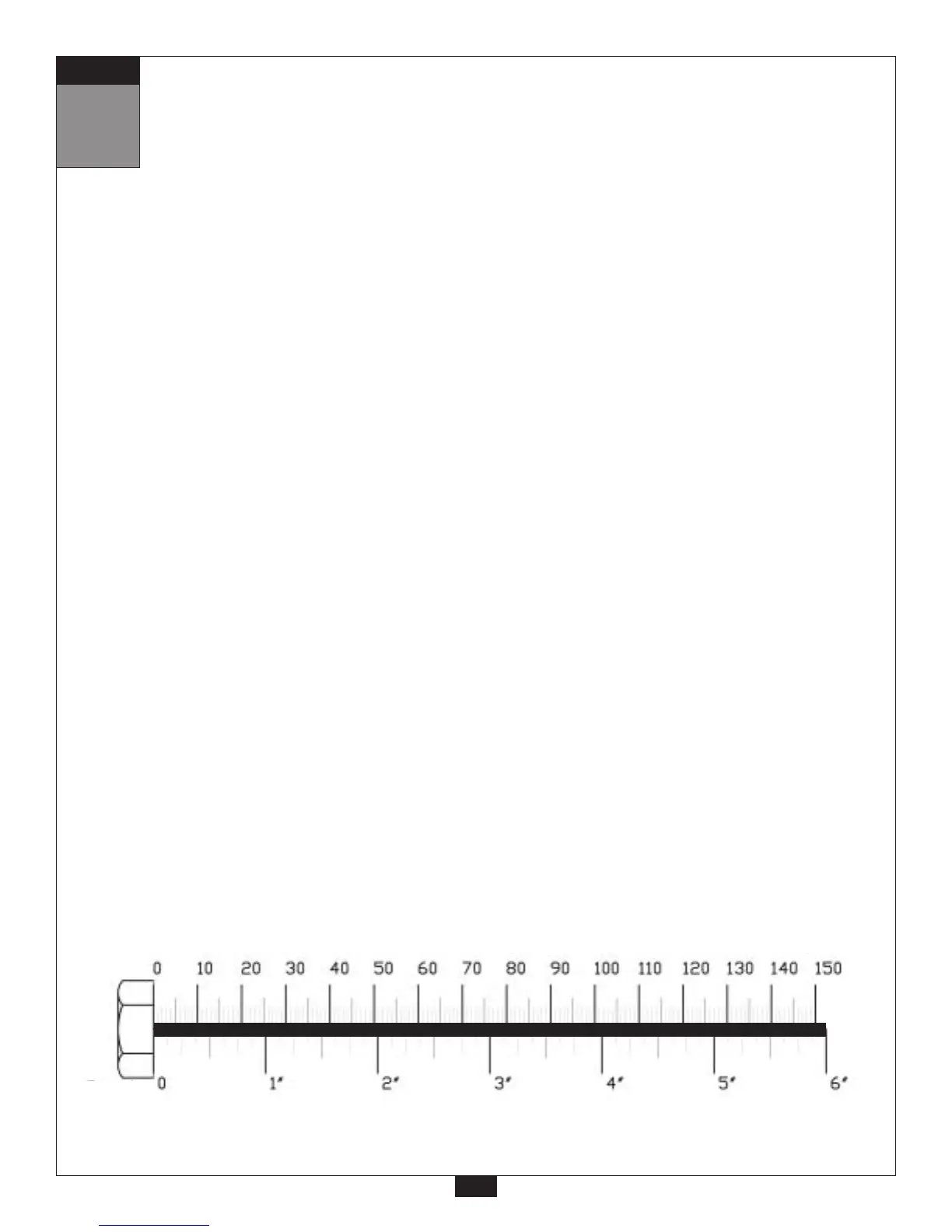
mm
Inch
26
STEP
NOTE:
Leave all pulley bolts hand tight until step 15 is completed.
A. Install Pulley (A3) and Pulley (A5) into Seated Press Arm Support (H) using for each pulley:
One 54 (3/8” x 7 1/4” hex head bolt)
Two 74 (3/8” washer)
Two 83 (steel bushing)
One 71 (3/8” nylon lock nut)
B. Install Pulley (A8) into the pulley flange on T
op Frame (E) as shown using:
One 51 (3/8” x 1 3/4” hex head bolt)
Two 74 (3/8” washer)
One 71 (3/8” nylon lock nut)
C. Install Pulley (B6) onto Main Base Frame (A) as shown using:
One 51 (3/8” x 1 3/4” hex head bolt)
T
wo 74 (3/8” washer)
One 71 (3/8” nylon lock nut)
D. Install Pulley (B7) onto Main Base Frame (A) as shown using:
One 51 (3/8” x 1 3/4” hex head bolt)
T
wo 74 (3/8” washer)
One 71 (3/8” nylon lock nut)