16
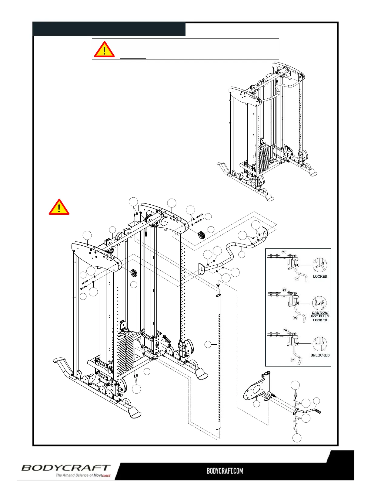
ProductAssembly STEP
1.AttachtheAdjustmentLever(25)andAxle(66)tothe
AdjusterFrame(24)usingthreeM5X25L
Screws(112),sixM5Washers(126)andthreeM5
NylonNuts(135).ThenslidetheAdjusterFrame
(24)ontotheUprightFrame(6)byengagingthe
CamberLevertoreleasethepop-pin.
2.AttachUprightFrame(6)totheBaseFrame(1)
andTopFrame(13)usingfour3/8”X1”Sunken
HeadBolts(104).
3.AttachChin-UpBar(14)totheRightLeftTop
Panel(22R23L)usingfour3/8”X4”HexBolts
(94),eight3/8”Washers(118)andfour3/8”Nylon
Nuts(131).
4. Tightenallbolts
atthistime.
Toeasetheassemblyprocess,
donottightenboltsuntiltoldtodoso.
52
1
13
52
94
94
118
118
118
118
131
112
126
131
14
6
24
25
94
118
118
22R
23L
104
131
126
135
104
9
 Loading...