20
ProductAssembly STEP
L9
L7,L8
L8
L7
T11
L5
L4
BoltEnd
98
98
98
98
52
52
52
36
3L
3L
8L
131
10L
131
131
52
98
98
18
131
131
23L
23L
131
131
20L
L6
L4,L5
L3
L2
L1
BallEnd
LowCable (55)
BoltEnd
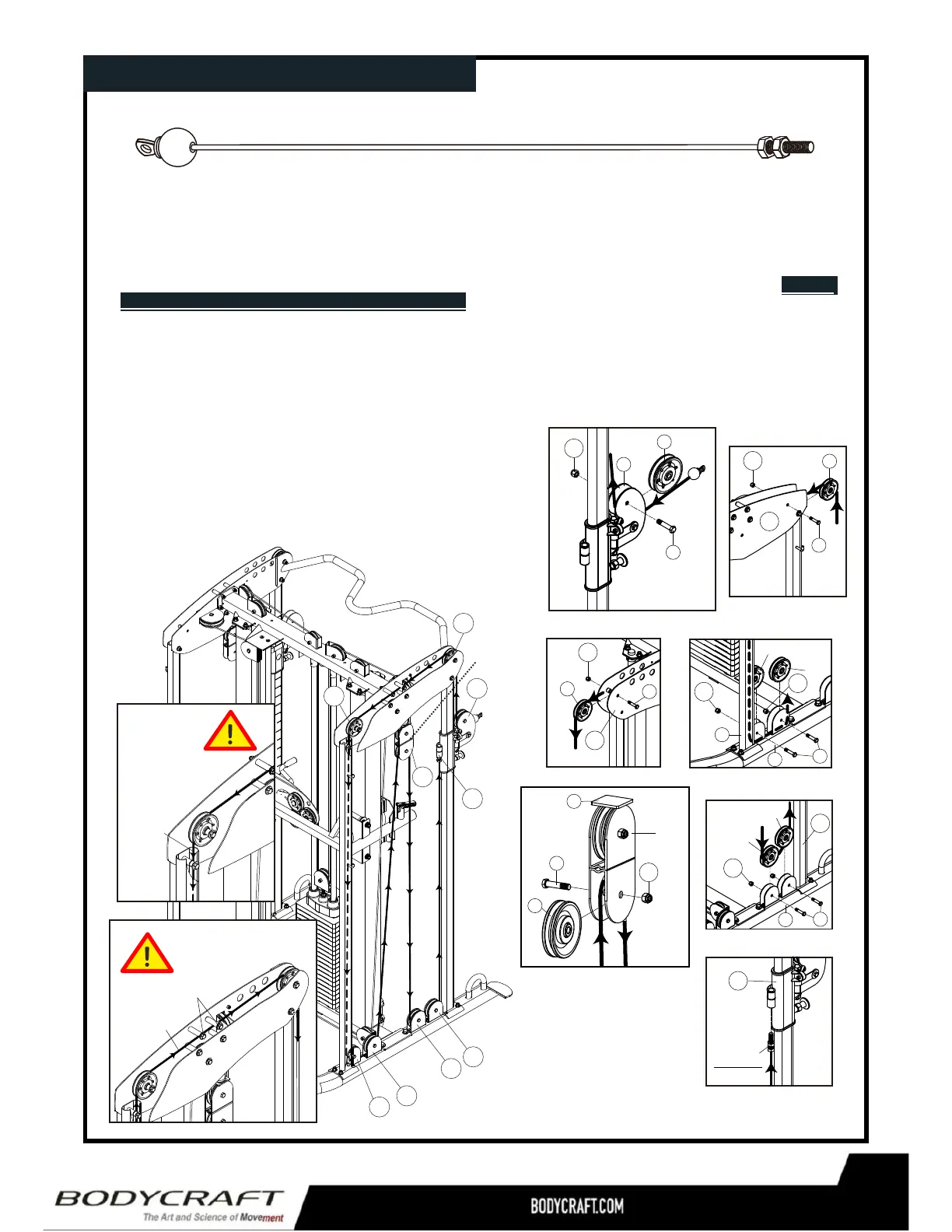
1.RefertoL1.StartbyroutingtheBoltEndoftheLowCable(55)throughRotatingPulleyHolder(18).
2.ThenroutethecableoverthetwopulleysmountedontheLeftTopPanel(23L),seeL2L3,making
surethatyouroutethecableUNDERthe2Bolts,seeFig2.ThenroutethecabledownintotheRear
LeftUprightFrame(10L),asshowninFig.1.Andunderthetwolowerpulleys,seeL4,L5.
2.RoutearoundthePulleyBlock(36)asFigureL6,anddowntothetwopulleysmountedatthe
LeftBaseLeg(3L),LeftRearUprightFrame(10L)asFigureL7,L8, thenuptothreadedBolt
HolderweldedontotheRightPulleyHeightAdjuster(20L)FigureL9.TheBoltmustinstalleda
minimumof1/3ofthewayintoBoltHolder.
3.PerformthesameprocedurefortherIghtside.
L9
L8
L7
L5
L4
L6
L3
L2
L1
Cable
Bolts
Thecablemustbe
undertwobolts.
Thecablewill
routeinside
thefront
portionof
thetube.
Cable
Fig.1
Fig.2
Pulley
Block
Pulley
Block
12
 Loading...