17
H10-12
H10-12
W10
W10
N10
1
18
19
2
H12-13
N12
W12
1
17
H10-12
H10-12
W10
W10
N10
1
18
19
15
2.3 Assembly
Before assembly, take a close look at the individual assembly steps shown and carry out the assembly
in the order given.
L NOTICE
+ First loosely screw all parts together and check that they t properly. Tighten the screws
using the tool only when you are instructed to do so.
+ If you have diculty recognising the graphics, we recommend that you open and/or
download the PDF instructions stored in the webshop on your end device (e.g. smartphone,
tablet or PC). There you have the option of zooming in closer.
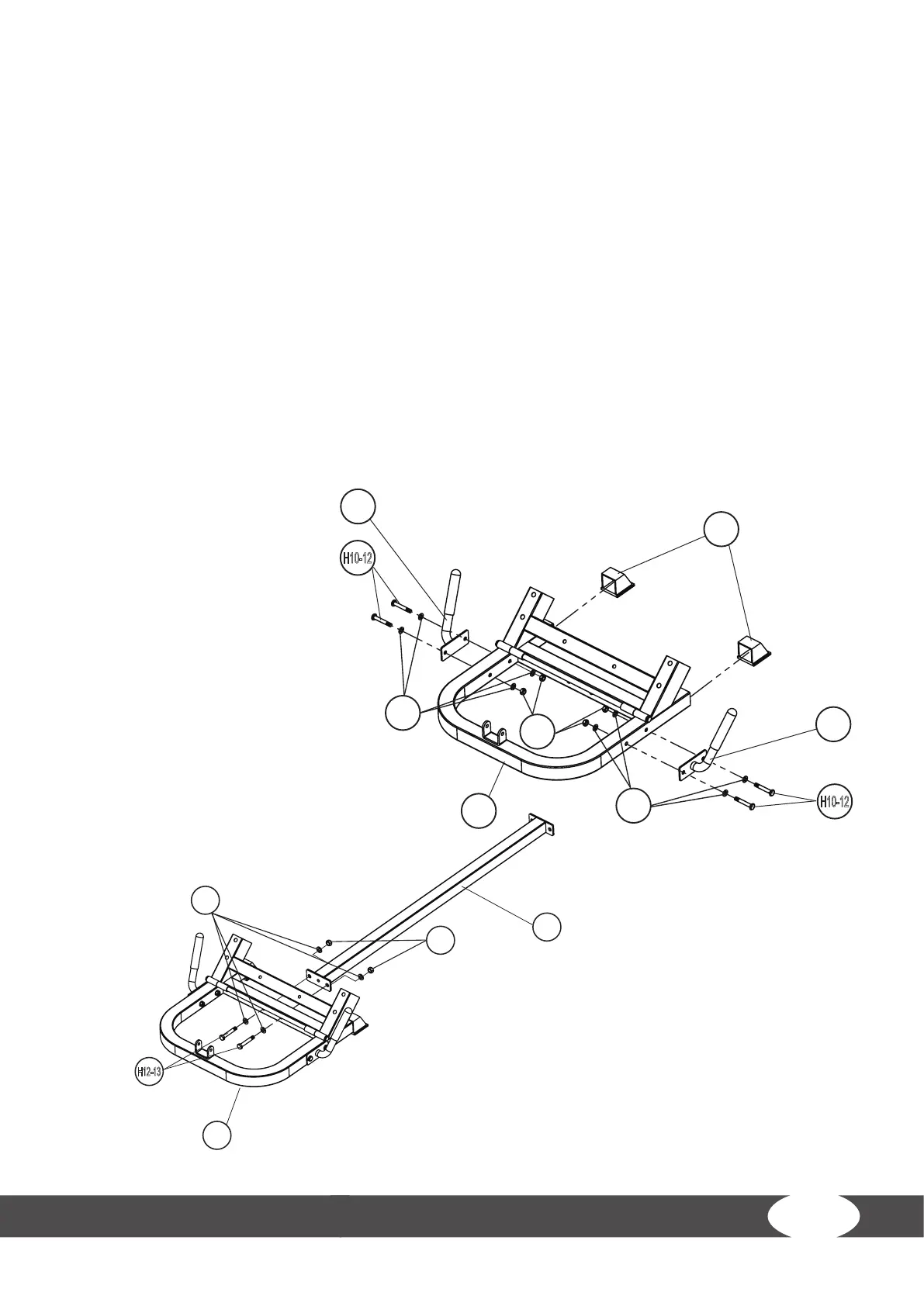
Step 1: Assembly of the Base Front and Base Connector
1. Attach two end caps (17) to the base front (1).
2. Attach the right handle (18) to the base front (1) with two bolts (H10-12), four washers (W10)
and two nuts (N10).
3. Attach the left handle (19) to the base front (1) with two bolts (H10-12), four washers (W10) and
two nuts (N10).
4. Attach the base connector
(2) to the base front (1) with
two bolts (H12-13), four
washers (W12) and two nuts
(N12).