Assembly step(2)explosion drawing
12
13
15
14
16
18
17
19
21
20
22
9
24
11
10
11
9
9
9
9
10
11
11
Fig. A
Assembly step(2)explosion drawing
12
13
15
11
16
18
17
19
21
20
22
9
24
11
10
11
9
9
24
24
24
9
9
11
10
Fig. B
18
CTX5
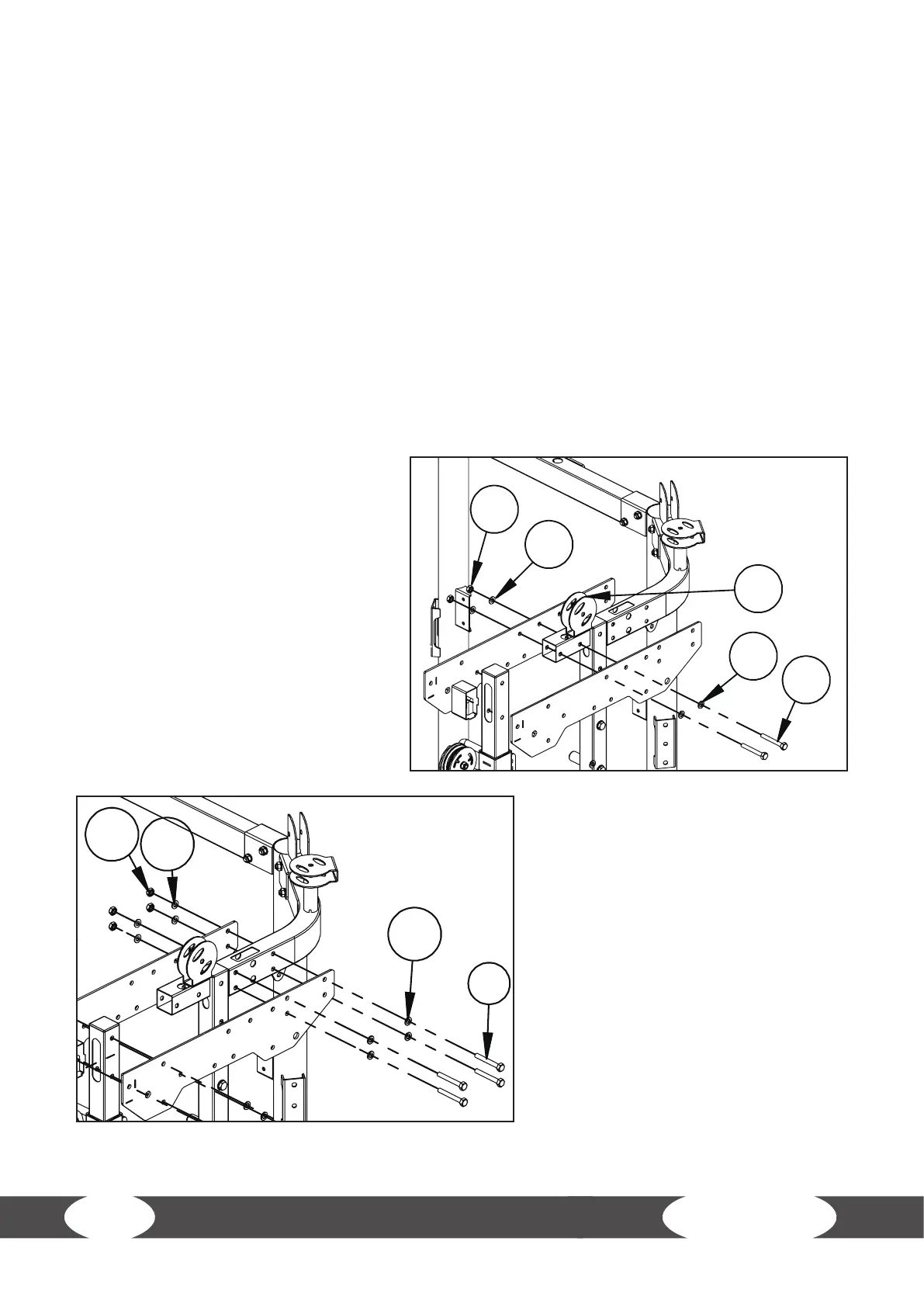
Step 2: Assembly of the Tubes and Chin Up Bar, Part 1
L NOTICE
+ Install all bolts and nuts before tightening. Do not over tighten.
1. Attach one upright tube (16) together with two upper plates (13) to the right upper bending
tube (7) with two bolts (9), four washers (11) and two nuts (10).
2. Attach the upright tube (16) together with two lower plates (19) to the right bending tube (5)
with two bolts (9), four washers (11) and two nuts (10).
3. Attach the right pulley frame tube (14) to the upper plates (13) with two bolts (9), four washers
(11) and two nuts (10) [g. A].
4. Attach the upper plates (13) to the right upper bending tube (7) with four bolts (9), eight
washers (11) and four nuts (10) [g. B].
5. Attach the right sliding tube (20) to the right tube with holes (17).
6. Attach the right tube with holes (17) and the foot tube cover (22) to the lower plates (19) with
four bolts (9), eight washers (11) and four nuts (10) [g. C].
7. Attach the lower plates (19) to the
right bending tube (5) with four
bolts (9), eight washers (11) and four
nuts (10) [g. D].
8. Repeat the steps 1 to 7 on the left
side.
L NOTICE
+ For the left side, use the left
pulley frame tube (15), left
sliding tube (21) and left tube
with holes (18).
+ Do not tighten bolts and nuts
yet.