28
CTX5
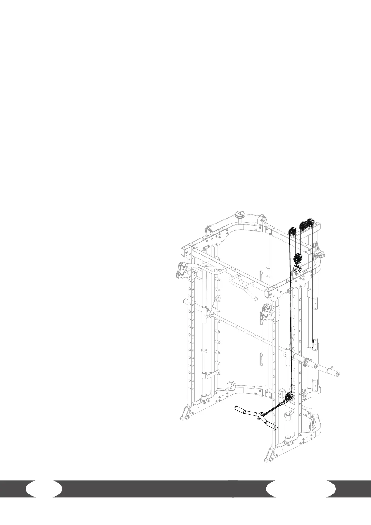
Step 6: Assembly of the Wires, Part 2
L NOTICE
+ Use the 4740mm wire (62) and 95mm pulleys (57).
+ The wire and pulleys must be assembled simultaneously.
1. Route the wire (62) under one pulley (57, A) and attach the pulley (A) to the pulley bracket (A-1)
with one bolt (59), two washers (11) and one nut (10).
2. Route the wire (62) over one pulley (57, B) and attach the pulley (B) to the pulley bracket (B-1)
with one bolt (59), two washers (11) and one nut (10).
3. Route the wire (62) under one pulley (57, C) and attach pulley (C) to the upper pulley bracket
(C-1) in the hanging pulley frame (63) with one bolt (59), two washers (11) and one nut (10).
4. Route the wire (62) over one pulley (57, D) and attach the pulley (D) to the pulley bracket (D-1)
with one bolt (59), two washers (11) and one nut (10).
5. Route the wire (62) over one pulley (57, E) and attach the pulley (E) to the pulley bracket (E-1)
with one bolt (59), two washers (11) and one nut (10).
6. Attach the bolt end of the wire (62) to the big sliding sleeve (46; F-1).
7. Attach the footplate (65) to the connection tube (1) with two bolts (49) and two washers (11).
8. Attach the chain (66) to the ball end of
the wire (62) with one of the snap hooks.
9. Attach the short bar (64) to the other
snap hook of the chain (66).