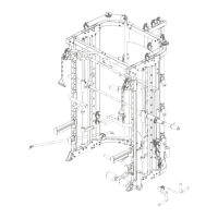
Assembly step(7)explosion drawing
Assembly step(7)explosion drawing
Assembly step(7)explosion drawing
30
CTX5
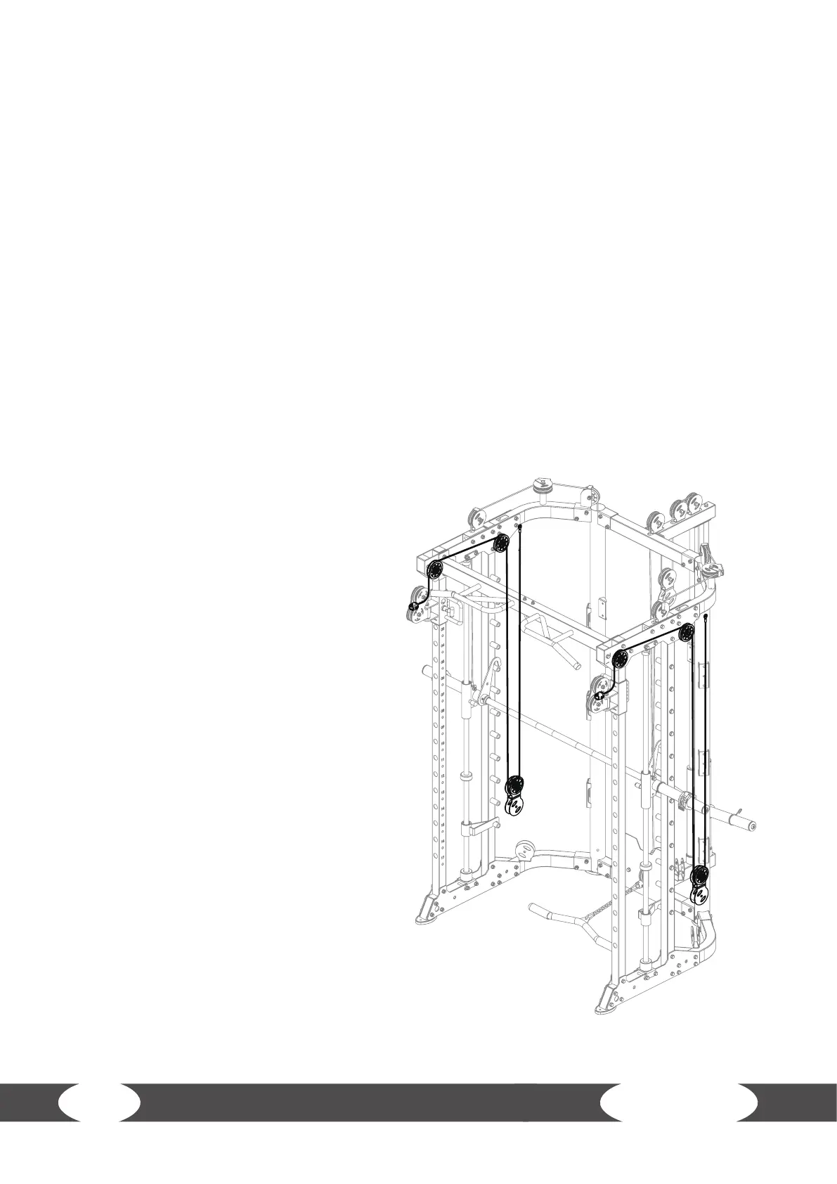
Step 7: Assembly of the Wires, Part 3
L NOTICE
+ Use the 4185mm wires (67) and 95mm pulleys (57).
+ The wires and pulleys must be assembled simultaneously.
+ Start with one side of the machine and repeat the steps on the other side.
1. Route the wire (67) over one pulley (57, A) and attach the pulley (A) between the upper plates
(A-1) with one bolt (24), two pulley spacer sleeves (68), two washers (11) and one nut (10).
2. Route the wire (67) over one pulley (57, B) and attach the pulley (B) between the upper plates
(B-1) with one bolt (24), two pulley spacer sleeves (68), two washers (11) and one nut (10).
3. Route the wire (67) under one pulley (57, C) and attach the pulley (C) to the upper pulley bracket
(C-1) in the hanging pulley frame (63) with one bolt (59), two washers (11) and one nut (10).
4. Attach the loop end of the wire (67) to the right upper bending tube (7; D-1) with one bolt (49),
two washers (11) and one nut (10).
5. Repeat the steps 1 to 4 on the left side of the machine with the second wire (67).