A
B
C
D
E
G
F
H
I
J
K
34
CTX5
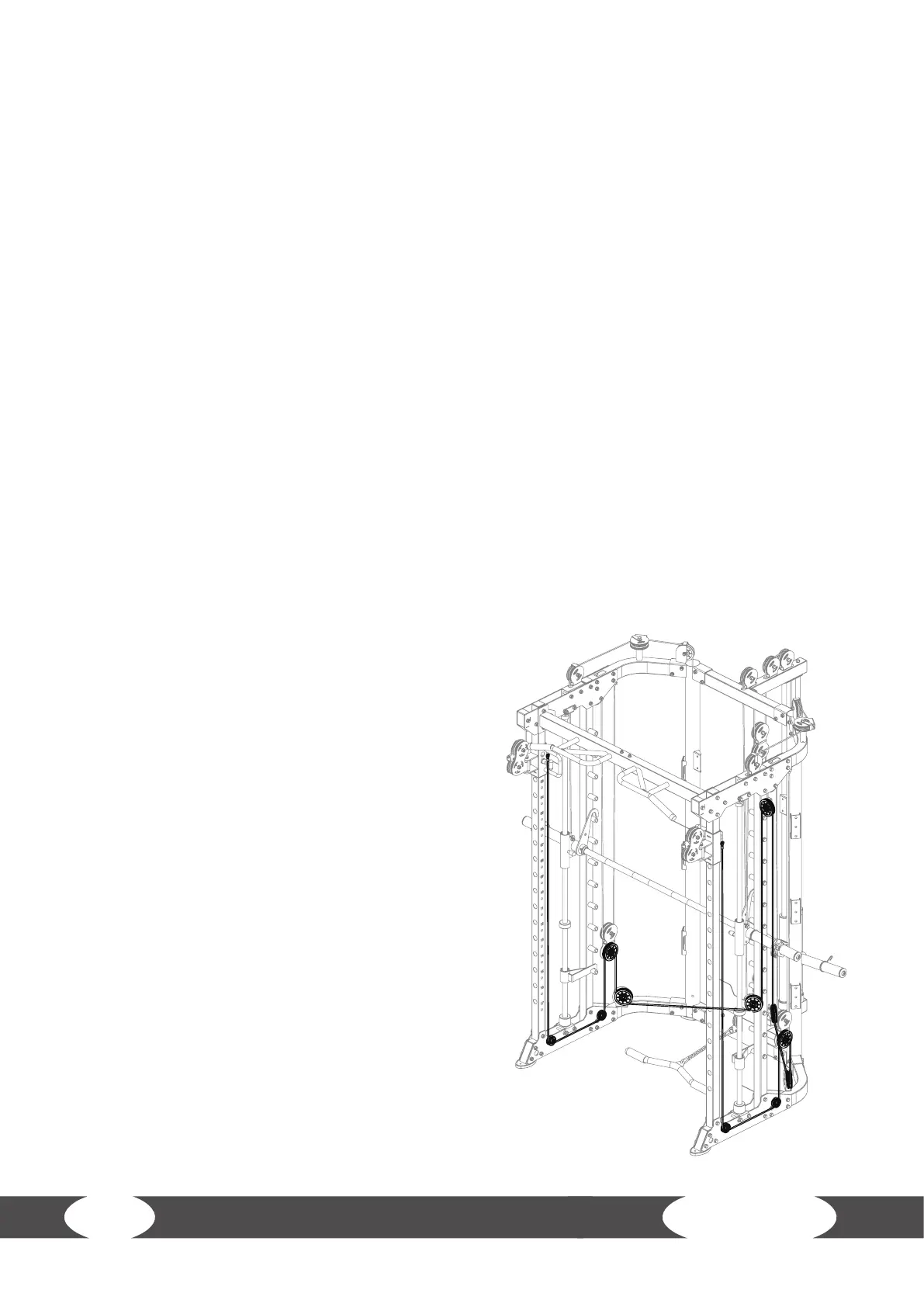
Step 9: Assembly of the Wires, Part 5
L NOTICE
+ Use the 9715mm wire (72), seven 95mm pulleys (57) and four 50mm pulleys (73).
+ The wire and pulleys must be assembled simultaneously.
1. Attach the end of the wire (72) to the right sliding tube (20) with one bolt (49), two washers (11)
and one nut (10).
2. Route the wire (72) under one pulley (73, A) and attach the pulley (A) between the lower plates
(A-1) with one bolt (24), two washers (11), two pulley spacer sleeves (68) and one nut (10).
3. Route the wire (72) under one pulley (73, B) and attach the pulley (B) between the lower plates
(B-1) with one bolt (24), two washers (11), two pulley spacer sleeves (68) and one nut (10).
4. Route the wire (72) over one pulley (57, C) and attach the pulley (C) to the lower pulley bracket
(C-1) in the hanging pulley frame (63) with one bolt (59), two washers (11) and one nut (10).
5. Route the wire (72) under one pulley (57, D) and attach the pulley (D) to the pulley bracket (D-1)
on the right bending tube (5) with one bolt (59), two washers (11) and one nut (10).
6. Route the wire (72) under one pulley (57, E) and attach the pulley (E) to the right pulley bracket
(E-1) in the double pulley bracket (53) with one bolt (59), two washers (11) and one nut (10).
7. Route the wire (72) over one pulley (57, F) and attach the pulley (F) to the pulley bracket (F-1) in
the pulley frame (69) with one bolt (59), two washers (11) and one nut (10).
8. Route the wire (72) under one pulley (57,G) and attach the pulley (G) to the left pulley bracket
(G-1) in the double pulley bracket (53) with one bolt (59), two washers (11) and one nut (10).
9. Route the wire (72) under one pulley (57, H) and attach the pulley (H) to the pulley bracket
(H-1) on the left bending tube (4) with one bolt
(59), two washers (11) and one nut (10).
10. Route the wire (72) over one pulley (57, I) and
attach the pulley (I) to the lower pulley bracket
(I-1) in the hanging pulley frame (63) with one
bolt (59), two washers (11) and one nut (10).
11. Route the wire (72) under one pulley (73, J) and
attach the pulley (J) between the lower plates
(J-1) with one bolt (24), two washers (11), two
pulley spacer sleeves (68) and one nut (10).
12. Route the wire (72) under one pulley (73, K) and
attach the pulley (K) between the lower plates
(K-1) with one bolt (24), two washers (11), two
pulley spacer sleeves (68) and one nut (10).
13. Attach the end of the wire (72) to the left sliding
tube (21) with one bolt (49), two washers (11) and
one nut (10).