Do you have a question about the Boge airtelligence PROVIS and is the answer not in the manual?
Safety instructions for operating and servicing the control unit.
Guidelines for the safe operation of the control unit.
Guidelines for the safe servicing and repair of the control unit.
Prohibited operations and conditions for the BOGE control, including explosive areas.
Automatic switching of compressors based on real-time air consumption and efficiency.
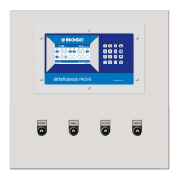
Explanation of buttons and their functions for operating the control panel.
Setting regulation range and buffer to control compressor switching based on pressure and consumption.
Defining the regulation range for compressors, showing examples of capacity and range.
Programming settings for variable speed compressors, including minimum and maximum capacity.
Ensuring compressor manufacturer data matches the programmed mA output signal.
Setting up four different pressure profiles and how they can be selected.
Programming the compressor order of sequence for optimal operation and control.
Details on the AE1 analog input, reserved for the pressure transducer.
Functions of the clock relay for time-controlled operations like switching compressors and outputs.
How the real-time clock is activated via the switching bridge and programming points.
Table for defining pressure profiles, including P min, P max, and P Alarm values.
Table for configuring compressor rank profiles, assigning ranks to compressors.
Table for programming clock relay switching points, day of the week, time, and functions.
Connecting a cable bridge or switch to start the compressed air station for energy-saving control.
Programming minimal and maximum capacity for regulated compressors with mA values.
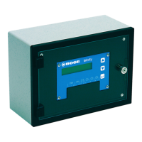
Description of different switching bridges (START, PROG, CLOCK, Manual) and their functions.
List of parameters to program for IP address configuration: IP-Address, Subnet mask, Gateway.
Configuring the station by entering a name, which forms part of the web address.
Entering the IP address of the airtelligence PROVIS controller for communication.
Display of fault alarms and service actions in the Alarm and Service Report.
Programming and activating alarm limiting values freely based on sensor values.
Managing alarms and services, sending messages via Fax, SMS, E-Mail, and defining alarm values.
Managing control parameters like pressure profiles, rank profiles, and clock settings.
Managing the SD card for loading, deleting, and sending/receiving configurations.
Server properties including station name, data folder, IP address, and Java Runtime installation.
Admin tool functions: updating web server, managing stations (install, update, rename), and password.
Updating the web server with current software archives downloaded from www.airleader.de.
Loading archives to Web-Server and starting the update process, which takes minutes.
| Manufacturer | Boge |
|---|---|
| Category | Control Unit |
| Type | PROVIS |
| Expandability | Yes |
| Ambient Temperature | 0 to 50 °C |
| Protection Class | IP20 |
| Housing Material | Plastic |
| Certifications | CE |
| Communication | Ethernet |
| Display | LCD |
| Operating Voltage | 24 V DC |
| Power Consumption | 15 W |
| Weight | 0.8 kg |