Do you have a question about the Boge FOCUS and is the answer not in the manual?
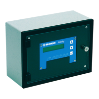
Describes how the FOCUS unit is installed as a control device in the switch cabinet.
Details the power supply terminals (A1, A2) and interruption via mains disconnectors.
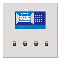
Lists basic and optional modules like keypad/display, RS485, relay, and pressure modules.
Explains the display unit with graphic display, indicator lamps, and operating keys.
Details the function of specific keys (ENTER, OFF, ON) and indicator lamps (Warning, Fault, Operation).
Describes the initial display and parameter adjustment after switching on the control.
Explains how to put the compressor into the READY state using the ON key.
Defines the 'ready-for-operation' status and automatic restart conditions.
Details the compressor motor start-up and the 'Run-up' display status.
Describes the phase after run-up where the compressor is in delta switching and shows 'load'.
Explains the idling phase, conditions for switching to it, or back to Ready.
How to switch off the compressor using the OFF key or remote control.
Mentions checking battery voltage and cleaning the display.
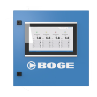
Describes the main display showing net pressure, system pressure, suction pressure, and compressor status.
Details how to access servicing information and display hours until next servicing.
Explains how to view motor running time, idling time, and efficiency display.
Describes how to measure energy loss due to potential leaks in the compressed air network.
Details procedures for starting single and continuous leakage measurements.
Shows information on the compressor set-up, including RS485 status and I/O.
Displays control settings, integrated timer status, and priority sequences.
Shows the current real-time clock setting including date and time.
Explains how to set the system's date and time using the control keys.
Describes how to access and view control/module software versions and addresses.
Explains how to enter 5-digit codes to access various settings and parameter lists.
Describes how to navigate and edit parameters after entering the correct code.
Details the process of selecting and changing individual parameter values.
Introduces and details parameters like Language and Pressure Range 1 settings.
Configures the type of external release for the compressor control.
Enables or deactivates monitoring of the external release appliance.
Determines the ON/Off switching function via keyboard, contact, or Bus.
Sets the function of the key switch for remote control or output release.
Defines the role of input 42 for pressure range switching or monitoring.
Sets the number of compressors to be controlled in base load switching mode.
Determines the time interval for changing compressor priorities in base load switching.
Sets pressure range parameters for base load switching control.
Explains how to set servicing intervals for compressor, motor, and receiver.
Describes how to restore factory or commissioning settings for the compressor.
Explains base load switch control settings and parameters.
Details how to adjust the switch clock for scheduling operations or priority sequences.
Explains compressor behavior when priority sequence 0000 is active.
Explains the function that limits motor start frequency based on air requirement.
Describes how the control handles automatic restarts after short power failures.
Explains the reserved spinning time after contactor operation.
Details how pressure ranges are selected via RS485, digital input, or internal timer.
Describes the tests available on the TAN unit (Screen, Keys, LED).
Explains how to test the safety valve using the ENTER key.
Details master control for multiple compressors via RS485 or relay modules.
Explains how switch clock affects pressure range and parameter settings.
Differentiates between warning and fault messages and their impact on compressor operation.
Describes how warning messages are displayed and acknowledged.
Explains the initial acknowledgement of a message while the cause is still present.
Details the specific process for acknowledging message 45.
Describes how fault messages are signalled, displayed, and the acknowledgement process.
Details terminals, types, functions, descriptions, and ratings for the basic module.
Lists terminals, types, functions, descriptions, and ratings for the RS485 module.
Details terminals, type, function, description, and rating for the analogue input module.
Specifies conductor cross sections for screw and tension spring terminals.
Provides a table of fault numbers, meanings, and compressor switch-off status.
Provides a table of parameters, their meanings, adjustment ranges, and code levels.
| Brand | Boge |
|---|---|
| Model | FOCUS |
| Category | Control Unit |
| Language | English |