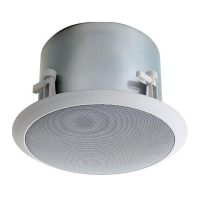
Installation
The HFCS1 can be installed in a variety of ceiling environments.The use of the TBCR
(Tile Bridge Support Ring) accessory may be desired for many of these environ-
ments.
For suspended ceilings, the use of a TBCR is strongly recommended to
help support and distribute the weight of the speaker.
In new construction situations, the TBCR, installed before sheetrock, acts as a rout-
ing template that ensures an accurate and neat hole for installation. The TBCR can
also be used as a support ring in retrofit applications to better distribute the speak-
er’s clamping forces. (See Accessory section on page 4.)
1. Begin by cutting a 10-¾" circular hole where the HFCS1 will be installed. If using
a TBCR, then follow its installation instructions for the specific type of environ-
ment the HFCS1 is being installed in.
2. Remove the speaker’s grille using a sharp tool to pry the grille out of its groove.
3. Make electrical connections to the pluggable terminal strip and plug it onto the
HFCS1. See section on Speaker Wiring on page 3.
4. Install terminal cover plates, if necessary or desired, using 4 screws. See the sec-
tion on Terminal Covers options on page 3 if using conduit or if it is required to
secure the speaker directly to the structure (typically for suspended ceilings).
5. Position the swing-out clamps so that they are against the body of the speaker
and insert the speaker into its opening in the ceiling.
6. Tighten the clamps by turning the clamping screws clockwise. Do not over-tight-
en the clamps - only tighten until the speaker is fairly snug in the mounting hole.
If using an electric driver, set the clutch to the lowest setting.
Do not replace the grille until the power level is set via the rotary selector switch
on the front panel. Refer to the Selecting Power Levels section on page 4 for instruc-
tions on selecting the power level.
2
IMPORTANT
• There must be a minimum of 11" of vertical clearance between the FRONT
of the mounting surface and any other structure for the speaker to fit. Before
cutting the full hole, use a smaller exploratory hole to determine if there are
any obstructions.
• The edge of the hole must be a minimum of 1-¼" away from any side obstruc-
tions to ensure that they will not interfere with the action of the clamps.