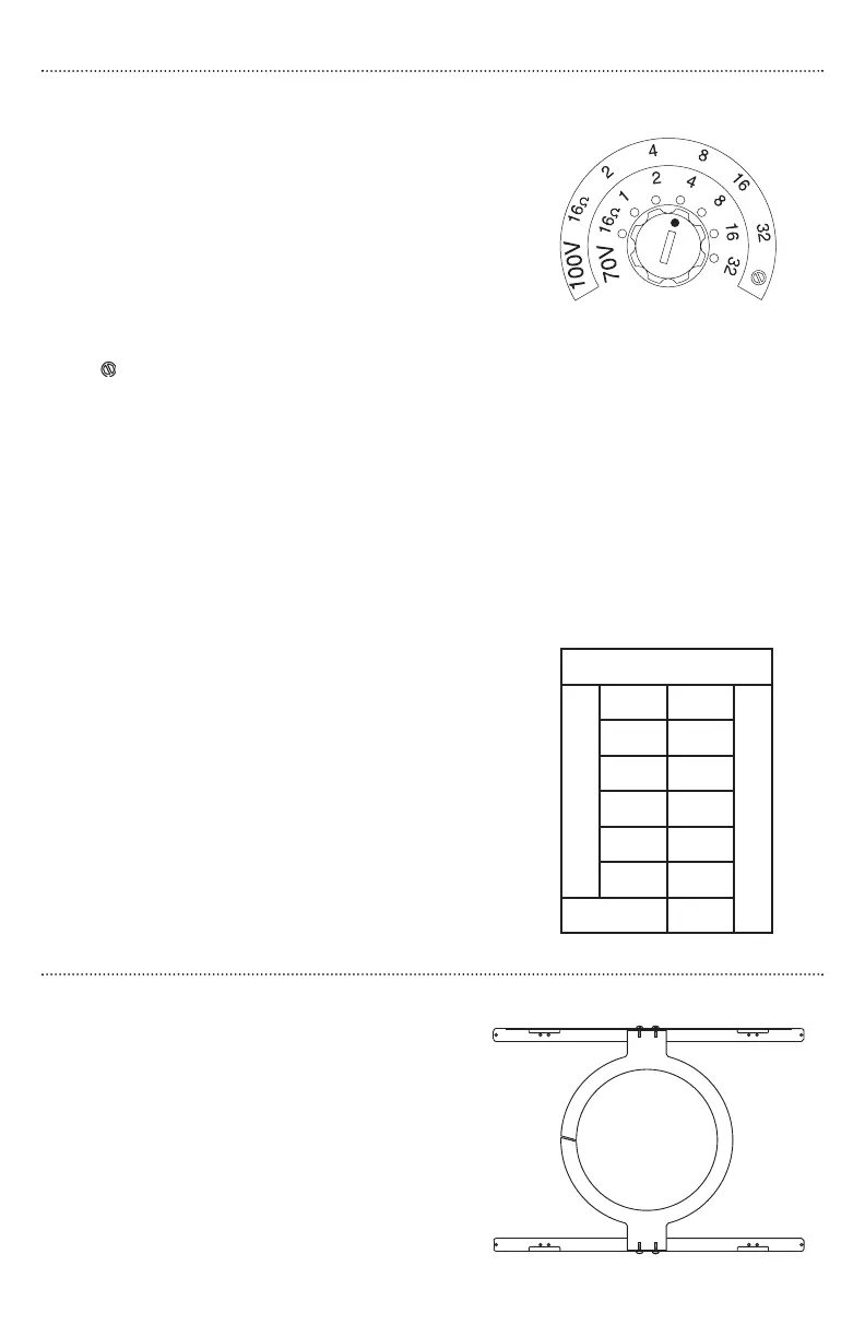
Selecting Power Levels
The front-mounted selector switch is used to
set the appropriate power level or impedance
for your system. Using a small, flat-blade screw-
driver, turn the knob until the slot points to the
power level you require.
70V/100V SYSTEMS
Both power setting scales for 70V and 100V sys-
tems are labeled on the speakers. On the 100V
scale, the last position clockwise is marked with
a symbol. Do not use this position in 100V
systems.
16
ΩΩ
SYSTEMS
The fully counterclockwise position of the setting switch is the 16-ohm position.This
setting is suitable for use with low-impedance amplifiers that tyically support 4- or
8-ohm speakers.The speaker’s higher, 16-ohm impedance makes it easier to combine
multiple speakers into series - parallel networks while keeping the total system
impedance at a level suitable for low-impedance amplifiers.
25V SYSTEMS
The HFCS1 will operate on 25V systems, but at
reduced power levels. The chart to the right
shows the conversion from a 70V power setting
to the actual 25V power level.
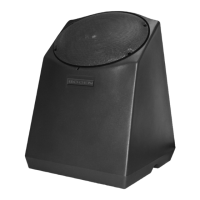
Accessory
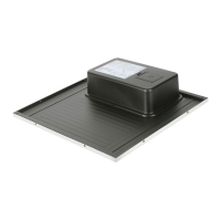
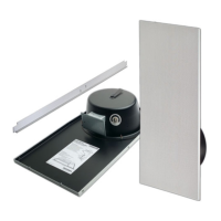
TBCR (TILE BRIDGE SUPPORT RING)
The TBCR is a combination tile bridge and
support ring that assists in securing the
HFCS1 and in distributing the weight of the
HFCS1 in various types of installations.
4
25V Conversion Table
70V Setting
32W 4W
25V Power
16W
2W
8W
1W
4W
1/2W
2W
1/4W
1W 1/8W
16Ω
39W